Chapter 8: Designing UAS Systems for Stealth
Student Learning Objectives – The student will be introduced to the design requirements for making a UAS stealthy, i.e. having reduced signatures for sonic, visual, thermal and radar detection.
Designing a UAS for Stealth
Stealth means “to resist detection.” Stealth applies to the air vehicle and materials visible to the enemy plus the internal SAA systems that control / create noise, heat, electromagnetic emanations, and changes in light. For ISR platforms and missions, it is essential the UAS systems be undetected in operation. “It is desirable not to alert the enemy (military) or criminals (police) to the ISR operation.” It can be assumed that the enemy is using counter-UAV operations and weapons. Stealth design protects the air vehicle from these counter – UAV measures. Stealth in civilian operations results in minimal environmental disturbances. (Austin, 2010)
From a personal privacy standpoint or in civil airspace it is desirable to have the UAV stealth features turned off. [It should be as if we had flicked a switch.] (Austin, 2010)
Detection Signatures
UAS / UAVs are detected by their signatures: noise (acoustic), optical (visible), infrared (thermal) and radar (radio). “These acoustic or electromagnetic emissions occur at the following wavelengths: (Austin, 2010)
A) Noise (acoustic) [16 m-2 cm, or 20 – 16000 Hz]
B) Optical (visible) [0.4 – 0.7 um]
C) Infrared (thermal) [0.75 um – 1 mm]
D) RADAR (radio) [3 mm – 3 cm]” (Austin, 2010)
If the designer is to “reduce the vehicle detectability to an acceptable risk level, it is necessary to reduce the received emissions or reflection of the above wavelengths (expressed as frequencies) below the threshold signature value. A good portion of the UAS signatures are a function of the operating height of air vehicle.” (Austin, 2010)
A student might look at the answers above and ask what is the significance? What does this really mean? Let’s take a short sojourn down EMS lane. Military planners used to think in terms of ground, sea, and air. Space came later. Now there is a “fifth realm” the electromagnetic spectrum (EMS). For EMS, we think in terms of frequency. The enhancement in our ability to communicate using the EMS is making significant changes in the way we conduct warfare. (Adamy D. -0., 2015)
Radio communications and wireless transmissions using tuned transmitters and information explosion of the Internet were the heart of a warfare-revolution. (Adamy D. -0., 2015)The certainty of intercept of radio communications and radar signals, and the ability to locate transmitters had a significant impact on military operations. (Adamy D. -0., 2015) Intercept, jamming, emitter location, message security, and transmission security became fundamental to warfare. (Adamy D. -0., 2015) The basic destructive capabilities (energy) employed in warfare have not changed a lot. (fast-moving projectiles, significant overpressure, heat, and sound). However, the ways they are employed have changed significantly through use of the EM Spectrum (EMS). (Adamy D. -0., 2015) Now, we guide the destructive energy of weapons towards their intended targets using the EMS in many ways. Also, the EW specialist uses EMS to prevent those weapons from hitting their intended targets (US), (Adamy D. -0., 2015) Sometimes the destruction of communications capability by an enemy is a goal.
The battlespace, which once had only four dimensions (latitude, longitude, elevation and time [before radio]) now has a fifth dimension: frequency. (Adamy D. -0., 2015) See Table 8-1 Battlespace Dimensions.
| Dimension | Function | Action |
| Latitude | Friendly Force Location | Direction of Weapons |
| Longitude | Enemy Force Location | Maneuver of Forces |
| Elevation | ||
| Time | Speed of Maneuver | Timeliness of Attack |
| Timing of Weapon Release | Enemy Vulnerability | |
| Frequency | Bandwidth Required | Rate of Information Flow |
| Bandwidth | Available Interference | |
| Frequency of Transmissions | Vulnerability to Jamming | |
| Vulnerability to Intercept |
Table 8-1 Battlespace Dimensions
Source: (Adamy D. -0., 2015)
Bandwidth is defined as the range within a band of wavelengths, frequencies or energy. Think of it as a range of radio frequencies occupied by a modulated carrier wave, assigned to a service over which a device can operate. Bandwidth is also the capacity for data transfer of electrical communications system. Range has a significant impact on radio transmission. Depending on the environment, the strength of a received signal, T, is a function of the square or fourth power of a distance, d, from the transmitter.
A closer transmitter will do a better job of receiving a signal and can usually locate the transmitter more accurately. (Adamy D. -0., 2015) Once we depend on inputs from multiple receivers, the network becomes central to our war making ability. [Think UAS Team collaboration.] We have now entered net-centric warfare. (Adamy D. -0., 2015)
Thinking again about a team or swarm of UAS, the low-hanging fruit target is US communications. We depend on connectivity in everything we do: daily lives, social interactions, business, manufacturing, government, transportation, computers and warfare to name just a few in the extensive list. Connectivity is any technique for the movement of information from one location or player to another. Consider the economic impact of having our critical infrastructure (banking, air transportation, etc.) shut down. Damaging the connectivity of system is real damage. We measure connectivity in terms of information flow. In warfare, this is called Information Operations (IO). Fundamental to IO is the frequency at which the information is transmitted or received.
Returning to stealth with respect to UAS design, we note that the intelligence, surveillance, reconnaissance and weapons payload-delivery functions of UAS. These are all IO operations and frequency is at the heart of their success against or denial by the enemy. (Adamy D. -0., 2015)
Electromagnetic Spectrum (EMS)
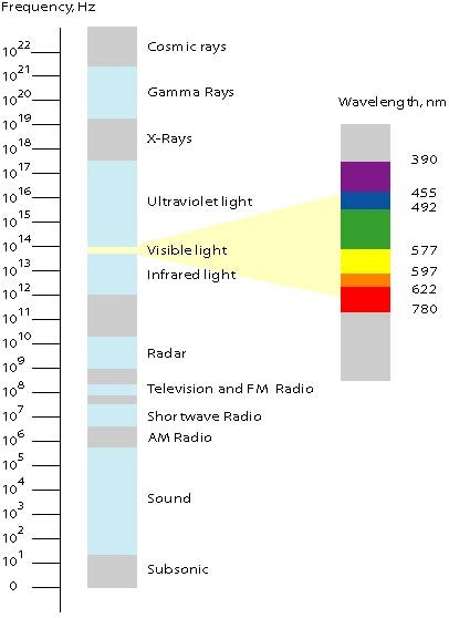
The German company, Tontechnic-Rechner-Sengpielaudio (TRS) has put together some clever tools for conversions of wavelength to frequency (visa versa) “for Acoustic Waves (sound waves) and Radio Waves and Light waves in a vacuum.” (TRS, 2018) Start with Figure 8-1 EMS. Note the inverse relationship between frequency, f and wavelength L (lambda – Greek).
Figure 8-1 EMS
Source: TRS. (2018, July 10). Tontechnic-Rechner-Sengpielaudio. Retrieved from Tontechnic-Rechner-Sengpielaudio Calculator. www.sengspielaudio.com/calculator-wavelength.htm
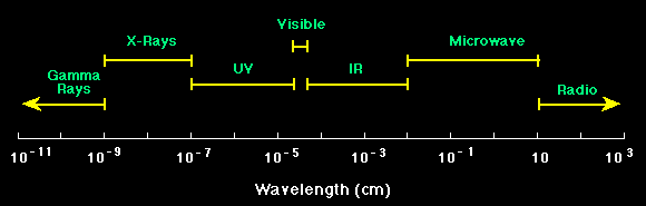
Note also how small the visible spectrum as part of the enormous EMS. Figure 8-2 shows some of the EMS functions.
Figure 8-2 EMS Functions
Source: TRS (2018, July 10). Tontechnic-Rechner-Sengpielaudio. Retrieved from Tontechnic-Rechner-Sengpielaudio Calculator, URL: www.sengspielaudio.com/calculator-wavelength.htm
Figure 8-3 shows the conversion for sound and acoustic wave period to frequency and back. (Adamy D. -0., 2015) Figure 8-4 shows the Sound EMS regions (Adamy D. -0., 2015)
Figure 8-3 Conversion for sound and acoustic wave period to frequency and back
Figure 8-4 Sound EMS Regions
Source for Figures 8-3 &4: TRS (2018, July 10). Tontechnic-Rechner-Sengpielaudio. Retrieved from Tontechnic-Rechner-Sengpielaudio Calculator. www.sengspielaudio.com/calculator-wavelength.htm
“Acoustic waves and Sound Waves in Air
Sound waves are EMS waves which propagate vibrations in air molecules. The 1986 standard speed of sound, c, is 331.3 m/s or 1125.33 ft/s at a temperature, T = 0 degrees Celsius.” (TRS, 2018)
“The formulas and equations for sound are: c = L x f; L = c /f = c x T; f=c /L,
T = time- period or cycle duration and T = 1/ f and f = 1 / T. The unit for frequency is Hertz = Hz =1/s. the unit for wavelength, L is meters, m. The time-period or cycle duration, T is sec, s. The wave speed or speed of sound, c, is meters/sec, m/s.” (TRS, 2018)
Austin states that the design limit for UAS Stealth for acoustic (noise) or sound waves is “[16 m-2 cm, or 20 – 16000 Hz].” (Austin, 2010) Use the bottom of the page converter {Basis: Speed of sound c = λ × f = 343 m/s at 20°C} for 16 m L = 21.4375Hz. This compares to the Austin value of 20 Hz. For the 2 cm = 0.02 m, the resulting valued for f = 17650 Hz. This is above the 16,000 Hz limit from Austin. This might be due to the 20-degree Celsius basis difference. This tells the UAS designer that the upper end of noise – Stealth acceptability 17,150 Hz. The Stealth range is 20 Hz – 17,150 Hz.
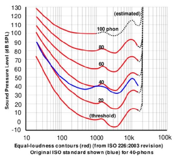
“Hearing range describes the range of frequencies that can be heard by humans, (aka range of levels). The human range is commonly given as 20 to 20,000 Hz, there is considerable variation between individuals, especially at high frequencies, and a gradual loss of sensitivity to higher frequencies with age is considered normal. Sensitivity also varies with frequency, as shown by equal loudness contours” (Rosen, S, 2011). See Figure 8-5.
“An equal-loudness contour is a measure of sound pressure (Db SPL) over the EMS spectrum, for which a listener perceives a constant loudness when presented with pure steady tones. The unit of measurement for loudness levels is the phon and is arrived at by reference to equal-loudness contours. Two sine waves of differing frequencies are said to have equal-loudness level measured in phons if they are perceived as equally loud by the average young person without significant hearing impairment.” (Staff, 2016) (Fletcher, 1933)
Figure 8-5 Equal Loudness Contours
Source: By Lindosland – http://en.wikipedia.org/wiki/Image:Lindos1.svg, Public Domain, https://commons.wikimedia.org/w/index.php?curid=2565926
“Radio Waves and Light Waves in a Vacuum
The formulas and Equations for radio waves and light waves in a vacuum are the same. However, the constant c is different. Lower-case c is the speed of light waves and the speed of radio waves in a vacuum. The speed of light in free space (vacuum) is the speed at which electromagnetic waves propagate, including light waves.” (TRS, 2018) “Instead of the speed of sound in air, the speed of light c, is 299,792,458 m/s (or 983,571,056 ft/s.) needs to be used in the formulas as speed of propagation. Wave frequency in Hz = 1/s and wavelength in nm = 10 (**-9) m.” (TRS, 2018)
“Radio waves and microwave radiation are both forms of energy known as Electromagnetic Radiation (EMR). Sunlight contains other EMR forms: ultraviolet rays, infrared (heat) waves, as well as visible light waves. These EMW spread in a vacuum at the speed of light ~ 300, 000 km/s as electromagnetic radiation.” (TRS, 2018) The propagation speed of electrical signals via optical fiber is about 9/10 of c or ~270, km/s. “Copper as a medium is worse slowing the propagation speed c, to ~200, 000 km/s.” (TRS, 2018) Sound is also shown on the EMS chart, but it has no electromagnetic radiation. “Sound pressure is the deviation from local ambient pressure (sound pressure deviation) caused by a sound wave – mainly in air.” (TRS, 2018) Wavelength is sometimes given in Angstrom units. 1 A = 10 (**-10) m = 0.1 nm. See Figure 8-6 EMS Reduced.
Figure 8-6 EMS Reduced
Source: TRS (2018, July 10). Tontechnic-Rechner-Sengpielaudio. Retrieved from Tontechnic-Rechner-Sengpielaudio Calculator, URL: www.sengspielaudio.com/calculator-wavelength.htm
Visible light, gamma rays, microwaves, and radio waves are all part of the EMS. They simply differ by wavelength. (TRS, 2018) Figure 8-7 is a conversion chart for Radio waves and light waves in a vacuum.
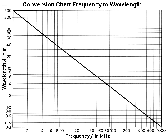
Figure 8-7 Conversion Chart – Frequency to Wavelength Radio
and Light Waves in a Vacuum
Source: TRS (2018, July 10). Tontechnic-Rechner-Sengpielaudio. Retrieved from Tontechnic-Rechner-Sengpielaudio Calculator. http://www.sengspielaudio.com/calculator-wavelength.htm
Some useful factors: 1 Terahertz (THz) = 10**3 GHz = 10**6 MHz = 10 **12 Hz; and
1 nm = 10 (**-3) um (micron-meter) = 10 (**-6) mm (millimeter)= 10(**-9) m
1-micron, um = m / 1000000 (1 millionth of a meter).
We have covered Austin’s noise, optical and infrared stealth signatures. RADAR is not as simple without another trip down RADAR lane. RADAR is extensively discussed and written about in the 20th century. It is certainly one of the most influential inventions in the last century, arguably more relevant than the cellphone. Our concern is to “paint” or recognize the UAS signature from a distance. If we can “see” the hostile UAS coming, it can be tracked, disabled, destroyed or intercepted and “turned” to a new waypoint or objective.
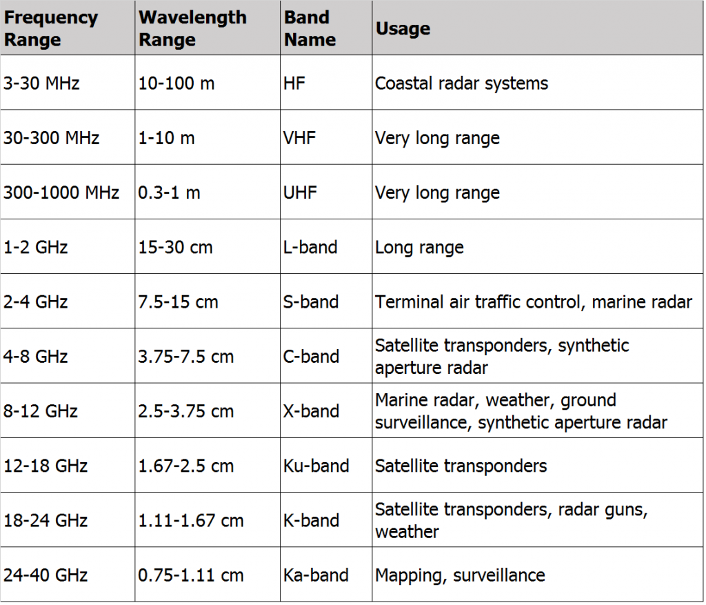
Figure 8- 8 RADAR Frequency Bands

Source: (ITU, 2019)
RADAR / EW / Range Equation
From Austin, we know that the upper frequency for a UAS RADAR signature is 0.03 m = 3 cm. This is approximately 10 GHz frequency. See Figure 8-8. RADAR is usually thought of in terms of frequency Bands. See Figure 8-9 RADAR Bands and their Usage. (ITR , 2019)
Figure 8-9 RADAR Bands
The key to understanding Electronic Warfare (EW), its role in detecting a UAS approaching a target, is understanding of radio propagation theory. If we understand how radio signals propagate, we can then intercept, jam, or protect in a logical progression. (Adamy D. -0., 2015) Adamy has written five stellar references on EW, use of dB logarithmic mathematics to solve EW equations for strength, gains, losses, radars, interceptors, jamming technologies, current threats, defense systems and more for the reader to research and enjoy. (Adamy D. -0., 2015)
RADAR is Radio Detection and Ranging. It is the use of radio waves and their propagation in the EMS to determine the battlespace elements for an approaching aircraft, UAS, ship, submarine, or any moving vehicle. We are only interested in two equations to understand the RADAR (radio) signature of a UAS. They are the link equation and the RADAR Range Equation, both presented without derivation. “The operation of every type of RADAR, military communications, signals intelligence, and jamming system can be analyzed in terms of individual communications links.” (Adamy D. -0., 2015) “A Link includes one radiation source, one receiving device, and all events to the electromagnetic energy as it travels from source to receiver.” (Adamy D. -0., 2015)
“Sources and receivers can take on many forms. When a radar pulse reflects off the skin of a UAS or airplane, the reflecting mechanism is a transmitter. It obeys the same laws of that apply to a walky-talky when the transmit button is pushed. Yet there is no power source and no circuitry to the reflection.” (Adamy D.-9. , 1998)
One – Way Link Equation
“The basic communication link, known as a one-way link, consists of a transmitter, receiver, transmitting and receiving antennas, and propagation losses between the two antennas along the path.” (Adamy D. -0., 2015) See Figure 8-10 Path Through Link.
Figure 8-10 Path Through Link
Source: Naval Air Warfare Center Weapons Division, Avionics Department (2013). Electronic Warfare and Radar Systems Engineering Handbook – Two-Way Radar Equation (Monostatic) http://www.rfcafe.com/references/electrical/ew-radar-handbook/two-way-radar-equation.htm
“The diagram shows signal strength in dBm and increases and decreases of signal strength in dB.” (Adamy D.-9. , 1998) Figure 8-10 shows the Line-of-Sight link. “The transmitter and receivers can electronically see each other. However, there are interferences / exceptions. The link must not be too close to water or land or in severe weather or asymmetric non-line-of-sight propagation factors. To calculate the received signal level (in dBm), add the transmitting antenna gain (in dB), subtract the link losses (in dB), and add the receiving antenna gain (in dB) to the transmitter power (in dBm).” (Adamy D.-9. , 1998)
“A simple example of the link equation in dB format is:
Transmitter Power (1 Watt) = + 30 dBm
Transmitter Antenna Gain = +10 dB
Spreading loss = 100 dB
Atmospheric loss = 2 dB
Receiving Antenna Gain = +3 dB
Received Power = =30 dBm + 10 dB – 100 dB – 2 dB +3 dB = – 59 dBm” (Adamy D.-9. , 1998)
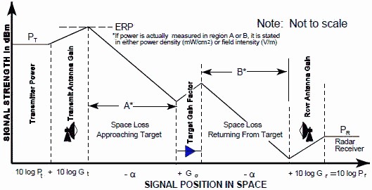
Figure 8-11 One – Way RADAR Equation
Source: Naval Air Warfare Center Weapons Division, Avionics Department (2013). Electronic Warfare and Radar Systems Engineering Handbook – One-Way Radar Equation. http://www.rfcafe.com/references/electrical/ew-radar-handbook/two-way-radar-equation.htm
Effective Range
The question is what is the maximum range that a RADAR can “see” a UAS in any form: individual, group, team or Swarm? The RADAR range equations can be used to estimate maximum distance to detect a UAS. The smaller the UAS the less reflective area is present to “return “a radar pulse back to its transmitter source. See Figures 8-11 and 8-12 which give the one-way and two-way (return trip) for determining the maximum range of a RADAR unit. At the maximum link range, the received power is equal to receiver sensitivity. “Receiver sensitivity is defined as the smallest signal (lowest power strength) that it can receive and still provide the specified output.” (Adamy D. , 2001)
Figure 8-12 Two Way RADAR Equation (Bi-Static)
Source: Naval Air Warfare Center Weapons Division, Avionics Department (2013). Electronic Warfare and Radar Systems Engineering Handbook – Two-Way Radar Equation (Bi-Static), http://www.rfcafe.com/references/electrical/ew-radar-handbook/two-way-radar-equation.htm
If the received power level is at least equal to the receiver sensitivity, communication takes place over the link. The amount of design signal delta over the minimum receiver sensitivity is called the margin. Both Figures 11 and 12 show the derivations (in normal and dB forms) of the RADAR Ranging Equations for limited environments. Other forms of the basic RADAR Ranging Equation, derivations, definition of terms and examples of radar units for surveillance, tracking and jamming applications can be found in Toomay’s simplified reference. (Toomay, 1982) Readers interested in the RADAR units for mariners (picking up a hostile UAS over a ship) can refer to Monahan’s (Monahan, 2004) or Burch’s references. (Burch, 2015)
Example – Given the operating frequency is 100 MHz, the atmospheric and normal terrestrial loses are minimal. Assume the transmitter output power, Pt = 10 watts. [About double the normal marine VHF set.] The transmitting gain antenna, GT is +10dB, the receiving antenna gain, GR, is +3 dB, and the design receiver sensitivity, Sens = – 65 dBm. {If we find that the received power level (say -59 dBm is at least equal to the sensitivity, then the communication takes place. The margin is this example would be 6 dB higher}. Assume line-of-sight between the two antennas. Calculate the maximum range we can see to the hostile UAS, not using Stealth techniques to reduce the radar visibility. Let PR = received power in dBm. Let d = distance in km. Setting Sens = PR = -65 dBm. Convert to dB math. Plug in the values and solve for 20 log (d). [Logs are base 10 not base e}
Sens = -65 dBm = PR = PT + GT -32.4 -20 log (f) – 20 log (d) + GR
20 log (d) = PT + GT -32.4 -20 log (f) + GR – Sens
And PT = 10 W = +40 dBm, GT = 10 dB, Gr = +3 dB, [20 log (f=100] = +40 dB
20 log (d) = +40 +10 – 32.4 -40 +3 +65 = 45.6
D = antilog (20 log (d)/20) = Antilog (45.6/20) = Antilog 2.28 = 190.54 km = 118.6 miles
We can see the UAS (multiple with bead on leader) at 119 miles from our radar transmitter.
We have come full circle back to the question of designing a UAS for stealth and to get closer to the target.
Closer
In this example, 119 miles gives the US defender some time to respond to his radar set bleep. However, as a hostile actor, suppose the plan is to reach within 5-10 miles of the US target. If a slow UAS is travelling at 60 mph, in the 5 seconds that it takes to spot the UAS on the defender RADAR set, the UAS has travelled about 1 ½ football fields.
{60 mph / 60 min /hour = 1 mile/ per min = 5280 ft /min / 60 sec / min = 88 ft / s x 5 sec = 440 feet / 3 feet /yard = 146.66 yards / 100 yards football field = ~ 1 ½ football fields travelled} Many USAs are designed to travel at over 100 mph.
To reduce the UAS RADAR detectability “(signatures”) “to an acceptable level it is necessary to reduce the received emission or reflection of the above frequencies (wavelengths) below a threshold value. This is often just a function of the height the UAS operates at.” (Austin, 2010) Hostile UAS fly lower and at greater speeds. The idea is to hit the target with surprise from above. “An unmanned air vehicle has advantages, compared to manned equivalents, in its inherent ability to achieve lower signatures. These advantages are:
- It has dense packaging. No air crew or their support equipment means a dimensionally smaller vehicle. In general, the vehicle mass is less for UAS missions;
- It has shape. UAS shape is not limited to accommodations for crew and need for access or external vision ports. UAS designs consider aerodynamic efficiency and detection – signature reduction.” (Austin, 2010)
Acoustic Signature Reductions
“Aircraft noise may be the first warning of its presence; however, it may not immediately be directionally/locatable for detection.” “UAS noise emanates predominantly from vortices, tips of wings, rotors, or propellers. Lowering wing span or blade span enhances acoustical stealth.” Conventional propulsion systems are a concern because of the noise of combustion. Electric motors develop virtually no noise. “Reducing mass and aerodynamic drag of the UAS reduces noise generation.” (Austin, 2010)
The human ear is a problem for the designer. “It is most sensitive to frequencies around 3500 Hz and can hear sound down to a practical threshold of 10 dB. For a given sound pressure level, attenuation of sound with distance in air and insulating material varies as the square of the sound frequency. Low frequency sound presents a greater problem for UAS stealth design.” (Austin, 2010)
MALE and HALE systems do not present acoustic issues “noise from their high frequency generators is attenuated by the time it reaches earth. The greater noise problem is posed by smaller UAS using piston engines.” (Austin, 2010) Sound comes from their internal combustion and exhaust systems. Sound emanation can be achieved with sound-absorptive materials, silencers and mufflers and directing the intake and exhaust manifolds upward. “Lastly, the level of sound detected depends on the level of background noise for sound contrast.” (Austin, 2010)
Visual Signature
“The human eye operates within a small range of the EMS, between 0.4 and 0.7-micron (um) meters peaking at a maximum efficiency approximately 0.55 um. Criteria that determine whether a human can see a UAS in the sky regardless of cloud conditions: a) size and shape of the UAS, b) background contrast and sharpness of edges that contrast; c) atmosphere; d) movement; e) exposure time; f) stability and soberness of observer; and g) glint.” (Austin, 2010)
“Size and shape of the UAS combine to determine a threshold of detectability (sic, at a flying altitude of the UAS) Contrast C, is defined as a ratio of the difference in luminance between an object and its background to the luminance of its background. So,
C= (B – B1) / B1 = delta B / B1
Where B is the luminance of the object and B1 is the luminance of the background, cd/m**2.” (Austin, 2010)
Laboratory tests have shown that “there is a 50% probability of detection by the unaided human eye if it subtends an angle of about 0.15 mrad.” (Austin, 2010) Other effects of atmosphere, movement, exposure time, stability of observer, and glint require further study.
Thermal Signature
“Infrared (IR) radiation is emitted from a heat source and propagates in the same way as light. The detectability of the radiant body is determined by its contrast with the background.” (Austin, 2010) “IR radiation is absorbed well by the atmosphere, particularly water and CO2 molecules, more so than visible light. The major windows for IR to pass through the atmosphere are in the 3-4 and 8-12 micron -meter wavelength bands. Receivers are designed to operate in one of these two bands.” (Austin, 2010)
Design factors include materials to insulate the power plant exhausts and using low-emissivity materials. Sky is cold and offers an excellent contrast for IR detection. However, the technology has not matured, and long-range IR detectors are limited to a 5-degree field of view. “The detection range is a function of temperature (K) to the fourth power. Reducing the target emissions temperatures is an effective evasion tactic for IR detection.” (Austin, 2010)
Radio / RADAR Signature
“The radio signature relates to the radio frequency emissions from the UAS and SAA systems and should be minimized.” RADAR / Radio signature is reflected frequency “generated by an emitter which is scanning the sky from ground and looking for a return (reflected) pulse from a body entering its sector.” (Austin, 2010) “The stealth designer aims to prevent these pulses being reflected to the detector.” (Austin, 2010) There are three methods to minimize UAS reflection of pulses to a receptor:
- “Use radar- translucent materials such as Kevlar or glass. Problem is that to protect a UAS sufficiently, the thickness of materials may be prohibitive;”
- “Cover the external surfaces with radar-absorptive materials. Unfortunately, this solution is both material and frequency dependent” and
- “Shape the aircraft externally to reflect radar pulses in a direction away from the transmitter.” This is more efficient proposal than a) or b). The goal is to reduce cross-section areas to not be at 90-degree angles to the radiation. The latter yields a clean pulse return. “It is also a design goal to avoid surfaces meeting at 90 degrees as this act as a radar “corner reflector” to give strong returns.” (Austin, 2010)
Low flying UAS – Use Navigation Collision Avoidance RADAR
The author has been experimenting with a low flying UAS[1] flying over calm (< 10 knot winds) Chesapeake Bay water at 100 above mean sea level. With a tailwind the Drone can clock upwards of 50-60 mph. The DJI Phantom 4 Pro Plus (PRO+) Drone is not designed for stealth. Experiment results: Can the Drone be detected? Yes. At what distance? Using the marine reference Boaters Bowditch equation for RADAR Geographic Range over water, the author calculated the detection range from the pulses of the boat’s radar to the UAS.
Distance (nautical miles) = 1.22 X [ square root (Height of the Antenna (ft)) + square root (Height of the Target (ft)) ]. (Hubbard, 1998)
If the antenna on a cruiser is at 20 ft and the UAS is flying at 100 ft at 55 mph toward the boat on a bow heading, what is the detection range? Answer 17.7 nautical miles.
The question then is how low should an aircraft / UAS fly to avoid radar detection?[2] The answer is “it depends.” It depends on the radar and the aircraft itself. Search radars are often usually located on well elevated land-forms to extend the line-of-sight (LOS) distance to the horizon. A conventional (non-stealthy) UAS aircraft flying just above surface level (100 ft up above water could theoretically be seen, as it comes over the horizon line, if there were no obstacles, radio towers, seaplanes, or large freighters to obscure it. The atmosphere attenuates the transmissions from the radar and can distort them.) The atmosphere over land has contaminants that can obscure radar pulses; dust, sand, smoke, rain, bugs, birds, water vapor, fog, clouds etc. These contaminants bend, scatter, and/or absorb transmissions showing up as “noise” on the radar screens. Noise reduces the effective range of the radar. Some noise can be electronically filtered so that the UAS can be distinguished from the noise. Chesapeake Bay has clean atmospheric conditions in fair weather – no contaminant density.
Assume a radar antenna mount on a hill might at 230 ft above ground level. [This is the height of three Radio Towers on land near Annapolis, MD.] If the aircraft is flying 100 ft above the ground, it will be at 30.7 nautical miles distance from the radar as it comes over the horizon. At that distance it will be seen clearly because atmospheric disturbances at that short distance are not an issue. That is what a US capital ship at sea might encounter if looking at a strike fighter or cruise missile coming at 11 nm/m with 3 minutes to impact. Let’s now mount the radar on a mountain top (say ski Round Top in Camp Hill, PA). Its antenna is approximately 2600 ft above mean ground level. The UAS aircraft flying at 100 ft will come over the horizon and be detected at ~ 74.4 nautical miles. 100 ft is not realistic unless over the sea on a calm day.
Stealthy UAS aircraft are a problem for radars. Stealth doesn’t make them invisible, but it greatly reduces the limit of detection. In the case of our first example, a fast stealth UCAV fighter coming over the horizon at ~18 nm will probably not be seen immediately. The human lag time for the radar operator could be 1-2 minutes, bringing the UCAV within 60 seconds of the radar receiver or ship before discovery – not much time for lethal countermeasures
Discussion Questions
- Why is RADAR detection of a UAS over water different from in the air?
- Check the Austin signature limits and track them down on the EMS charts.
- What stealth measures would be employed for a UAS / drone specific to maritime service – say in the Spratly Islands?
Bibliography
Adamy, D. -0. (2015). EW 104 EW against a New Generation of Threats. Boston: Artech House.
Adamy, D. (2001). EW 101 A First Course in Electronic Warfare. Boston, MA: Artech House.
Adamy, D.-9. (1998, Jan). Lesson 4: the basic link for all EW functions. (electronic warfare)(EW Reference & Source Guide). Journal of Electronic Defense, Jan 1998 Issue.
Austin, R. (2010). “Design for Stealth”, Unmanned Aircraft Systems UAVS Design Development and Deployment. New York: John Wiley and Sons.
Burch, D. (2015). RADAR for Mariners. New York: McGraw-Hill.
Fletcher, H. a. (1933). Loudness, its definition, measurement and calculation. Journal of the Acoustical Society of America , 5, 82-108.
Hubbard, R. K. (1998). Boaters Bowditch. Camden, MA: International Marine.
ITU. (2019, July 19). ARTICLE 2 – Nomenclature – Section I – Frequency and Wavelength Bands. Retrieved from ITU Radio Communication Edition 2008: https://web.archive.org/web/20111001005059/http://life.itu.int/radioclub/rr/art02.htm
Monahan, K. (2004). The Radar Book: Effective Navigation and Collision Avoidance. Anacortes, WA: Fineedge Publications.
Rosen, Stuart (2011). Signals and Systems for Speech and Hearing (2nd ed.). BRILL. p. 163. For auditory signals and human listeners, the accepted range is 20Hz to 20kHz, the limits of human hearing
Staff. (2016, April 17). Equal Loudness Contours. Retrieved from Gutenberg Organization: http://central.gutenberg.org/article/WHEBN0001046687/Equal-loudness%20contour
Toomay, J. (1982). RADAR for the Non – Specialist. London; Lifetime Learning Publications. London: Lifetime Learning Publications.
TRS, S. (2018, July 10). Tontechnic-Rechner-Sengpielaudio. Retrieved from Tontechnic-Rechner-Sengpielaudio Calculator: www.sengspielaudio.com/calculator-wavelength.htm
Weise, E. (2017, August 23). could-hackers-behind-u-s-navy-collisions. Retrieved from USATODAY: https://www.ruidosonews.com/story/tech/news/2017/08/23/could-hackers-behind-u-s-navy-collisions/594107001/
Readings
Adamy, D. (2001) EW 101 A First Course in Electronic Warfare, Boston: Artech House.
Adamy, D. (2004) EW 102 A Second Course in Electronic Warfare, Boston: Artech House.
Adamy, D. (2009) EW 103 Tactical Battlefield Communications Electronic Warfare, Boston: Artech House.
Adamy, D. (2015) EW 104 EW against a New Generation of Threats, Boston: Artech House.
Adamy, D. (2003) Introduction to Electronic Warfare Modelling and Simulation, Boston: Artech House.
Austin, R. (2010) UAVS Design, Development and Deployment, New York: Wiley.
Burch, D. (2005) RADAR for Mariners. New York, McGraw-Hill.
Hubbard, R.K (1998) Boaters Bowditch, Camden, MA: International Marine.
Monahan, K (2004) The RADAR Book: Effective Navigation and Collision Avoidance. Anacortes, WA: Fineedge Publications.
Toomay, J.C. (1982) RADAR for the Non – Specialist. London; Lifetime Learning Publications
