Chapter 17: High – Altitude Platforms (HAPS) – A Promise not Reached
Student Learning Objectives
The student will be introduced to High-Altitude Platforms (HAPS) for wireless communications. This overview will include the key design considerations, architecture, channel considerations, link budget, opportunities and challenges (not met) for this promising technology. Not covered are the detailed channel modelling calculations or the complex antenna designs required. The latter two subjects can be found in Chapters 3 and 4 of (Alejandro Aragon-Zavala, 2008)
Introduction
For three decades wireless communications designers have researched the inclusion of unmanned aircraft systems into their network architectures “to provide cost- effective wireless connectivity for devices without infrastructure coverage. Compared to terrestrial communications or satellites, low altitude UAS are generally faster to deploy, more flexibly reconfigured and have better communication channels due to presence of short-range LOS links. However, the use of highly mobile and energy constrained UAVs for wireless communications introduces new challenges.” (Yong Zeng, 2016) Table 17-1 shows HAPS capabilities compared to terrestrial and satellite systems for telecommunications. (Jesus Gonzalo, 2018)
Missions
“HAPS are capable of providing services that complement, compete or replace those currently offered by airplanes, satellites and terrestrial networks.” (Jesus Gonzalo, 2018) Three key areas on the list are telecommunications, Earth observation, and GNSS.
Telecommunications
HAPS platforms hold a promise for improvement of existing communications systems both in capacity and coverage. (Jesus Gonzalo, 2018) This same promise has been made for three decades. Technology has moved from 2nd, 3rd and 4th Generation wireless systems to 5th Generation systems. 5G software (aka 5G NR for New Radio) refers to software under the 3GPP industry association standard or the ITU IMT-2020 international requirements. (Romano, 2017) 2G, 3G and 4G technologies are associated with their respective advances: GSM, UMTS, LTE, LTE . (See Abbreviations list for definitions) (Romano, 2017) Advanced telecommunications services that can be offered from HAPS platforms are in various stages of development. Table 17-2 gives an overview of HAPS enhanced services that are envisioned by developers.
Table 17-1: HAPS Capabilities Compared to Terrestrial and
Satellite Systems for Telecommunications
| Issue | High Altitude Platform |
| Deployment | Faster deployment than space-based platforms. Less “build -out” than terrestrial networks. Very fast response to emergency situations |
| Upgrading | Access to platform/ payload after deployment enables service upgradeability like terrestrial. Enhanced flexibility and adaptability |
| Link Budget | Shorter distances to HAPS makes the Link budget favorable compared to satellite links. Smaller antenna coverage area permits high focus on areas of interest getting capacity higher density (x100) than GEO Satellites |
| Signal Processing | HAPS are quasi-stationary. This significantly reduces the Doppler shift due to platform motion |
| Ground Terminals | Smaller / simpler terrestrial terminals than satellite exhibit data rates |
| Antenna Pointing & Directivity | Mobile LTE services and TETRA are based on omnidirectional links |
| Latency | Very low, equivalent to terrestrial networks. Round-trip time ~ 0.26 ms versus ~30ms for LEO and ~250 ms for GEO |
| Geographic Coverage | Hundreds of miles per platform (~125 miles radius) between terrestrial (few miles) and space GEO (up to 33% of the Earth surface)” (Jesus Gonzalo, 2018) |
Source: (Jesus Gonzalo, 2018)
Table 17-2: HAPS Platform Advanced Telecommunications Services in
various stages of engineering and development (Jesus Gonzalo, 2018) (D, 2010)
| Dream | Service |
| Direct-To-Home (DTH) | DTH broadband: useful in unserved areas with no infrastructure or poor connectivity. Mimics a satellite or terrestrial tower |
| Trunking | Large number of users under a HAPS footprint can connect and share a single satellite connection. Good balance between coverage and signal degradation |
| Backhauling | HAPS provides very high capacity backhaul links between network nodes (cell towers) and backbone. Costly optical fiber or terrestrial microwave links are avoided |
| High Throughput | HAPS service to Offload congested GEO spot beams |
| Tactical | Communication usually in UHF, HAPS services are scalable, agile, reliable, affordable, defendable, rapidly deployable and requires minimum in theater ground infrastructure. (T.C. Dozer, 2008) |
| Mobile Broadband | Normally provided by terrestrial wireless networks. If none available existing satellite (Iridium, Inmarsat, etc.) can provide. HAPS provides a higher capacity equivalent due to favorable link budgets. |
| 5G | HAPS infrastructure supports 5G services.” (Jesus Gonzalo, 2018)[1] |
Source: (Jesus Gonzalo, 2018)
The deployment of services shown in Table 17-2 “have been hindered due to limitations derived from the telecom bands assigned to HAPS by the World Radio Conference (WRC) when providing such services according to Resolution 122 from WRC-07 and Resolutions 145 and 150 from WRC -12. Resolution 809 from WRC-15 in 2019 discusses the appropriate regulatory actions for HAPS within existing fixed-service allocations.” (Jesus Gonzalo, 2018)
Table 17-3 shows a more detailed view of the basic characteristics of terrestrial, satellite and HAPS systems. (Alejandro Aragon-Zavala, 2008) Several of these characteristics are covered later in this chapter.
Table 17-3: Basic Characteristics of Terrestrial, Satellite and HAPS Systems (Alejandro Aragon-Zavala, 2008) |
|||
| ISSUE | TERRESTRIAL | SATELLITE | HAPS |
| Propagation Delay | Not an issue | Large delay causes noticeable impairment in voice communications for | Low, since altitude for HAPS is much lower for satellites |
| Health and safety | Low power handsets are used | GEO and MEO. High power handsets needed to overcome large path losses | Similar to terrestrial except for large coverage areas |
| Technology risk | Mature technology | New technology for LEO & MEO. GEO behind terrestrial in cost, volume & performance | Terrestrial wireless technology supported by spot beams. Research on smarter antenna in progress |
| Deployment timing | Development staged -substantial build-out to provide coverage | Entire system needs to be built to operate | BIG advantage: needs only one platform and one ground station to initiate operations |
| System growth | Easy upgradable. Cell splitting to increase capacity | Capacity is increased by adding new satellites. Hardware upgrades are possible if replacing satellites | Spot beam resizing and adding more platforms used to increase capacity; hardware upgrades easier than satellites |
| Complexity | User terminals are mobile. Operations well understood | Mobile satellites in LEO and MEO are complex. | Modern mobility platforms; operations not complex. Platforms need refueling. |
| RF Channel quality | Good signal quality through proper antenna placement | GEO distance limits spectrum. Ricean fading. | Free space like channel at distances ~ terrestrial |
| Indoor coverage | Might be achieved. Research in progress on outdoor-to-indoor penetration | Not available due to large path loss at satellite communication frequencies | Coverage via repeaters but not outdoor-to-indoor penetration |
| Breadth of geographical coverage | A few miles per base station | Large regions in GEO. Global for MEO and LEO | 100’s of miles per platform |
| Cost | Varies. Much lower than satellite systems | >$200MM for GEO;
~$2 Billion for LEO |
~$50MM but less than terrestrial network |
| Cell diameter | 0.06214 -> 0.6214 miles | 31 miles for LEO; 310 miles for GEO | 0.6214 to 6.214 miles |
Source: (Alejandro Aragon-Zavala, 2008). Distances converted to miles by author.
Earth Observation
HAPS can be used as an “effective platform for Earth Observation (EO) payloads. It provides useful capabilities for many services and complementing satellite and conventional aircraft (manned and unmanned).” (Jesus Gonzalo, 2018) “Space sensors can map large areas worldwide. They offer a relatively course resolution. They suffer operational constraints due to weather (clouds), and fixed-timing acquisitions.” (Jesus Gonzalo, 2018) Regular aircraft are more flexible but also costlier. When continuous monitoring by MALE aircraft requires deployment of multiple platforms. (Jesus Gonzalo, 2018) EARSC has identified a variety of EO services that fit well with a HAPS solution. (EARSC, 2015) HAPS has the advantage when required coverage area is local or regional. “HAPS platforms can fly for very long periods, up to several months and its capacity for EO is comparable to conventional aircraft.” (Jesus Gonzalo, 2018)
GNSS
“HAPS platforms provide functionality for navigation systems:
- Additional ranging sources to assist and improve position
- Network node to provide data from an external source
- Reference stations for network RTK (Real Time Kinematic) and PPP (Precise Point Positioning) types of services
- Additional sensor platform to perform radio occultation and / or GNSS reflectometry measurements.”(Jesus Gonzalo, 2018)
UAV-Aided Wireless Communications
Figure 17-1 to 3 from (Yong Zeng, 2016) illustrates three typical use cases of UAV-aided wireless communications, discussed below.
UAV-aided ubiquitous coverage
“Figure 17-1 shows two example scenarios where HAPS plays a significant role in recovered wireless communications. HAPS UAVs can be deployed where there is a need to assist the existing infrastructure and provide seamless wireless coverage. Two examples are rapid service recovery after partial or complete infrastructure damage due to natural disasters and base station offloading in extremely crowded areas (ex. NFL stadium support).” (Yong Zeng, 2016) (Osseiran, Dec 2014)
Figure 17-1: & 17-2: UAV-aided ubiquitous coverage with overloaded /
malfunctioning base station and UAV-aided relaying
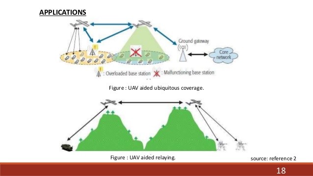
Source: (Yong Zeng, 2016) and (Y. Zeng, May 2016.)
UAV – aided relaying
“Figure 17-2 shows the case where UAVs are deployed to provide wireless connectivity between two or more distant users or user groups without reliable direct communication links. From a military example, links between frontline and the command center for emergency purposes would qualify for HAPS treatment.” (Y. Zeng, May 2016.)
UAV – aided information dissemination and data collection
“HAPS UAVs may be dispatched disseminate or collect delay tolerant information to / from a large number of distributed wireless devices.” (Y. Zeng, May 2016.) In Kansas, the agriculture industry uses HAPS for precision agriculture applications and water distribution.
Figure 17-3: “UAV – aided information dissemination and data collection 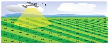 |
| Source: (Y. Zeng, May 2016.) |
Challenges
HAPS for wireless communications has faced some stiff design challenges. Along with the normal communications links as in terrestrial systems, additional control and non-payload (CNPC) links with more stringent latency and security requirements are needed for HAPS UAV systems.” (Yong Zeng, 2016) “These are needed for safety-critical functions, real-time control, and collision avoidance. The result is that effective resource management and security mechanisms must be designed for HAPS communications UAVs.” (Y. Zeng, May 2016.)
“Mobility is also a design challenge. HAPS requires highly mobile environment. This translates to highly dynamic network topologies. The latter are sparsely and intermittently connected. (Brown, Dec 2008) Effective multi-UAV coordination or UAV swarm operations need to be designed for reliable network connectivity.” (N. Goddemeir, June 2015) The author notes that in this textbook, Swarm operations have a very negative side too. One chapter has been devoted to C-UAS swarm operations.
“Another interesting challenge stems from the size, weight and power (SWAP) constraints of HAPS UAVS. These limit their communication, computation and endurance capabilities. To tackle SWAP constraints, energy -aware UAV deployment and operation mechanism are needed under SCADA control to efficiently use the energy and replenishment thereof.” (Yong Zeng, 2016).
“Cell interference is not negligible. Mobility and lack of fixed backhaul links under centralized control means that neighboring cells with UAV – enabled aerial base stations is more challenging than that of terrestrial systems. Interference management techniques and software requires expensive and complex customization for UAV -aided cellular coverage.” (Yong Zeng, 2016)
Simple HAPS UAV Network Architecture
It is time to explore the HAPS UAV basic networking architecture, channel characteristics, design considerations, performance enhancers to exploit mobility. We then take on the Link budget and work an example. There are hundreds of diagrams for HAPS network structure. The author has chosen a figure from (Yong Zeng, 2016) because it the easiest to build upon. “Figure 17-1 shows the generic networking architecture of wireless communications with HAPS UAVS. [2]Three basic types of links exist: the CNPC link, backhaul links and the data link.” (Yong Zeng, 2016)
Control and Non-Payload Communications Link (CNPC)
“CNPC links are essential to ensure the safe operation of all UAV systems. “CNPC links are highly reliable, low – latency and provide secure two-way communications.” (Yong Zeng, 2016)
Figure 17-4: Basic HAPS networking architecture of UAV-aided wireless communications”
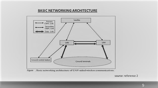
Source: (Yong Zeng, 2016)
“CNPC links usually have low data rate requirements. They exchange safety critical information among HAPS UAVS and ground control stations (GCS), such as dedicated mobile terminals mounted on ground vehicles.” (Y. Zeng, May 2016.)
“CNPC information flow can be categorized into four types:[3]
- Command and Control from GPS to UAVs
- Aircraft status report from UAVs to ground
- Sense – and – avoid (SAA) information among UAVs
- Necessary in case of emergency human intervention requirements
CNPC links operate in protected spectrum
Currently there are two bands that have been allocated:
- L-band (960-977 MHz)
- C-band (5030 -5091 MHz)
These bands apply to the primary GCS to UAVs (primary CNPC links) because of low delay factor. Secondary CNPC links via satellite act as backup to enhance reliability and robustness. (Yong Zeng, 2016) A key requirement for CNPC links is enhanced security. Efforts must be made to avoid the ghost control scenario (think James Bond film Goldeneye) where UAVs are controlled by a hostile force or unauthorized hacker. CNPC have enhanced authentication protocols and physical security.” (Y. Zeng, May 2016.)
Backhaul Links
Backhaul links are intermediate links that connect the core network or internet backbone to the small peripheral subnet systems at the edge of the system. “They are essentially a subset of the data links category that process dozens of gigabits per second in the UAV- gateway wireless backhaul.” (Yong Zeng, 2016)
Data Links
“Data links support mission-related communications for the ground terminals: These include: terrestrial base stations (BSs), mobile terminals, gateway nodes, wireless sensors,” (Y. Zeng, May 2016.) “and SCADA communications.” (Randall K. Nichols, 2018) Refer to Figure 17-1 for HAPS UAV – aided ubiquitous coverage. “The data links maintained by the UAVs support the following communication modes:
- Direct mobile- UAV communications for BS offloading or during BS malfunction
- UAV-BS and UAV-gateway wireless backhaul
- UAV – UAV wireless backhaul (Rappaport, 2014)
Data links support a wide range of bit rate / sec capacity. They have a higher tolerance for latency and security. They can reuse spectrum allocations in a given band and / or have dedicated spectrum for enhanced performance.” (Yong Zeng, 2016)
Channel Characteristics, Propagation and Channel Modelling
This section will give only a “flavor” of the subject of channel characteristics, propagation and modeling. For a detailed mathematical look at this interesting subject, consult chapter 3 in (Alejandro Aragon-Zavala, 2008). Subjects / factors covered include: Free space loss, Multipath, Rayleigh criterion, Rain attenuation, Gaseous adsorption, scintillation, general case of channel modelling, geometric characterization, platform altitude effects, two-ray model, Rice factor, Rician PDF (probability density function), statistical characterization, Lognormal PDF, LOS conditions, UHF channels, wideband models, Markov chains, Chapman-Kolmogorov equation, Semi-Markovian processes, switched broadband channel model, Politecnico di Torino (Polito) Multipath channel model, SHF and clear sky models, shadowing, time series, Gaussian model, fading mitigation techniques, uplink and downlink power control, on-board beam shaping, adaptive methods for coding and modulation, digital transmission rate reduction, site, platform, frequency and time diversity; and open, closed and hybrid loop models. (Alejandro Aragon-Zavala, 2008) Chapter 3 is a treasure house of information.
HAPS UAS / UAV systems work because of effective antenna design and placement. Like channel modeling, this subject is outside the scope of this chapter 17. In that same reference (Alejandro Aragon-Zavala, 2008) is an excellent chapter 4 on antennas for HAPS. (Alejandro Aragon-Zavala, 2008)
If chapter four is not enough to fill your palette, the author recommends the superior textbook by McNamara entitled: Introduction to Antenna Placement & Installation. (Macnamara, 2010)
“Both CNPC and data links in HAPS UAV-aided communications consists of two types of unique channels, UAV – ground and UAV – UAV.” (Alejandro Aragon-Zavala, 2008)
UAV-Ground Channel
Research on HAPS UAV – Ground channels is still ongoing after three decades. “This compares unfavorably to similar channel research for piloted aircrafts for aeronautical applications.” (Sun, June 2015) “Whereas piloted aircraft systems ground stations are usually in open areas with tall antenna towers, the HAPS UAV -ground links operate in a more complex environment. UAV-ground links do not always have LOS links available.” (Alejandro Aragon-Zavala, 2008) They may be blocked by terrain, buildings, or the airframe itself. The latter introduces a severe signals – link delay during aircraft maneuvering (a process called airframe shadowing). “Shadowing can be significant during mission-critical operations.” (Matolak, April 2015)
For low-altitude UAVs, the UAV-ground channels may constitute a number of multi-path components due to reflection, scattering, and diffraction by mountains, ground surface, and foliage. (Yong Zeng, 2016) Multi-path propagation is when radio signals reach an antenna by two or more paths causing interference, phase shift of the primary signal, or destructive fading. This effect can be modelled by the Rayleigh or Rician Distributions depending on conditions. (Alejandro Aragon-Zavala, 2008)
“For HAPS UAVS operating over the desert or sea, the two-ray model is used because of dominance of the LOS and surface reflection components.” (Alejandro Aragon-Zavala, 2008) [See Chapter 3 of (Alejandro Aragon-Zavala, 2008)].[4]
HAPS UAV – UAV Channel
“The UAV – UAV channel is dominated by the LOS component. Multi-path fading due to surface reflection is limited compared to the UAV – Ground channel experience. UAV – UAV channels experience higher Doppler frequencies than their UAV – ground counterparts due to large relative velocity between UAVs. These characteristics have a direct influence on the spectrum allocation for UAV – UAV links.” (Yong Zeng, 2016) There are two competing theories. “The dominance of LOS links suggests that the emerging mmWave (5G) communications should be employed to achieve high-capacity UAV – UAV wireless backhaul. (Yong Zeng, 2016) Or the high relative velocity between UAVs coupled with higher frequency in the mmWave band could lead to excessive Doppler shift.” (Yong Zeng, 2016) [5]
From the Designers Shoes
What would a designer of a communications system based on HAPS need to know? “Certainly, the designer would need to know the components, subsystems and interfaces involved and the sensors and instruments which could be part of the HAPS mission. In addition, the spectrum regulations and link budgets for licenses bands (clear sky and rain) would be fully worked using typical systems parameters for HAPS.” (Alejandro Aragon-Zavala, 2008) Maybe we can take a helicopter view and get a handle on the design problem.[6] Start with the stratosphere segment where we will play.
Stratosphere Segment
“The stratosphere segment includes platform requirements to establish communications with ground facilities and other HAPS. This segment has two main elements, the payload and the bus.
The payload is the mission.” (Alejandro Aragon-Zavala, 2008) It is the raison de entre into telecommunications and infrastructure. “The bus provides resources. Its functions are:
- Payload must be pointed in the correct direction, coverage to right users and interference restricted,
- Payload must be operable,
- Data from payload must be communicated to the GCS and back,
- Payload must operate reliably over a design time-period. An energy source must be provided to enable performance by payload functions.”(Alejandro Aragon-Zavala, 2008)
Figure 17-5 shows the subsystems that form the stratospheric segment for HAPS.
Platforms
“Environmental conditions present in the stratosphere affect HAPS (whether they are manned / unmanned aircraft or LTA airships). These conditions are atmospheric pressure, air density, specific lift, and wind speed.” (Alejandro Aragon-Zavala, 2008)
Figure 17-5: Subsystems of HAPS Stratosphere Segment
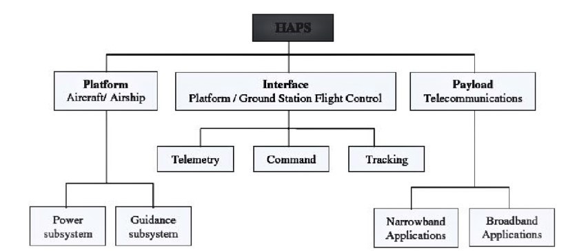
Source: (Alejandro Aragon-Zavala, 2008), page 142, renamed Figure 5.1
Many services require geostationary HAPS. “The platform must be kept in a control box with dimensions of 800 x 400 x 1000 m (0.4971 x 0.2485 x 0.6214 miles). The size of the platform determines the maximum payload weight at an altitude up to 20 km (12.427 miles). Both types of HAPS can be powered by different power systems, fuel, electric motors or solar energy. (Alejandro Aragon-Zavala, 2008) The sun is the preferred energy source. The drawback for sun is efficient storage of energy for long term use. The planned mission duration can be from 6 months to 5 years. Two types of platforms can be used in the stratosphere: aerostatic (LTA) and aerodynamic (UAV).” (Alejandro Aragon-Zavala, 2008)
Aerostatic Platforms (LTA)
“Aerostatic platforms carry heavier payloads ~1000 kg (2204.6 lbs). They have precise station-keeping for nominal environmental conditions and plenty of area for power generation. Medium- strong winds are a problem. Ground stations and infrastructure is expensive and complex. High-strain hull material is needed – a definite disadvantage.” (Alejandro Aragon-Zavala, 2008)
Aerodynamic Platforms (UAVs)
“UAVs are less expensive than LTAs with easy station-keeping in turbulent conditions. They require less ground infrastructure. Unfortunately, they have cannot carry much weight. Payloads are limited to less than 100 kg (~220 lbs). Power is also restricted (up to 1200W). Continuous movement of the platform is required, which translates to more power consumption.” (Alejandro Aragon-Zavala, 2008)
Platform Choice – Key Designer Issues
“Key issues to be considered by the designer when choosing the platform:
- Cost – deployment, acquisition and operations
- Environmental compatibility – emissions, re-usable energy, non – pollutants
- Power – fuel powered or solar-powered
- Service offering – affects payload capacity”(Alejandro Aragon-Zavala, 2008)
- “Technological similarity to space-based systems – autonomous operations, payload types, accommodation, reliability, payload operations, communications budget.”(Alejandro Aragon-Zavala, 2008) [7]
Telecommunications Payload
“The telecommunications payload consists of phased array antennas (transmit / receive) for gateway links with the ground and or terrestrial subscriber stations with a bank of processors that handle receivers, multiplexing, switching and transmitting functions. The payload can use different multiple access techniques.” (Alejandro Aragon-Zavala, 2008) Table 17-4 dives deeper into the what the designer must be aware of in terms of HAPS communication payload constraints / requirements / elements / subsystems. The list is extensive, and our hypothetical designer is still not in deep water.
| Table 17-4: HAPS design communication payload constraints / requirements / elements / subsystems. (Alejandro Aragon-Zavala, 2008) |
|
| ISSUE | Constraint / Requirement / Element |
| “System Constraints | Considerations different from satellite or terrestrial systems (refer to Table 17 -1) |
| Customer requirements | Mission lifetime, connectivity with other operating systems, coverage area served, control station site location, capacity, services offered, availability, (Alejandro Aragon-Zavala, 2008) |
| Technical | Maximum available transmit power, receiver sensitivity, interference, environment, available components and spares, trade-off between cost and technology performance and noise performance. (Alejandro Aragon-Zavala, 2008) See for definitions / derivations: (Adamy, EW 101 A First Course in Electronic Warfare, 2001); (Adamy, EW 102 A Second Course in Electronic Warfare, 2004) (Adamy, EW 103 Tactical Battlefield Communications Electronic Warfare, 2009) |
| International Regulations | HAPS systems must control interference between different systems (satellite, terrestrial) and ensure compatibility between national systems connected end-to-end. (Alejandro Aragon-Zavala, 2008) |
| Antenna subsystem | Affects total mass and stability. Consider critical. (Alejandro Aragon-Zavala, 2008). See Chapter 4 in (Alejandro Aragon-Zavala, 2008) |
| HAPS transponder | Along with antenna subsystem constitutes the communications payload, includes low and high passband filters, beamforming, low noise amplifiers (LNA), multiplex method, FDM (frequency division multiplexing for UL), power amplifiers / demultiplexer for DL. (Alejandro Aragon-Zavala, 2008) See chapter 4 in (Alejandro Aragon-Zavala, 2008) |
| LNA | Low-noise temperature and sufficient gain keeps contributions small from prior stages in transponder. (Alejandro Aragon-Zavala, 2008) |
| Frequency converters | Frequency change devices also known as mixers, to differentiate traffic for UL /DL. (Alejandro Aragon-Zavala, 2008) |
| IF processor | Provides HAPS transponder gain. (Alejandro Aragon-Zavala, 2008) |
| Filters | Limit spurious adjacent signals and noise. (Alejandro Aragon-Zavala, 2008) |
| Transmitters | Amplifying signals to level of DL transmissions. (Alejandro Aragon-Zavala, 2008) |
| Payload system performance | Performance parameters on individual equipment. (Alejandro Aragon-Zavala, 2008) |
| Key payload electrical parameters | 1) “Antenna coverage area, gain, dimensions, electrical efficiency and feeder losses
2) Figure of merit G/T – ratio of the receive antenna gain to system noise temperature ~ affects link performance 3) EIRP – Effective isotopic radiated power ~ determines the power capability of the HAPs 4) Power per backhaul carrier in user link.” (Alejandro Aragon-Zavala, 2008) See Chapter 3 in (Alejandro Aragon-Zavala, 2008) |
| Other important parameters | 1) “Isolation between channels ~to reduce potential adjacent channel interference issues
2) Spurious outputs ~ to reduce interference levels to contiguous wireless systems 3) Amplifier linearity 4) Group delay variation – time delay experienced by the modulating waveform passing through equipment. This causes signal dispersion and degrades performance.” (Alejandro Aragon-Zavala, 2008) |
Source: (Alejandro Aragon-Zavala, 2008) compressed text information from pp. 144-146
Telemetry, Tracking and Command (TT & C)
“The interface between the ground station flight control and HAPS platform is performed by TT and C subsystems. This subsystem is responsible for two-way flow of information from HAPS to the GCS. It also links HAPS to the Flight Control Station (FCS) via LOS conditions and under spectrum control as regulated by the ITU-R. Table 17-5 shows the functions of the TT & C Subsystem.” (Alejandro Aragon-Zavala, 2008)
| Table 17-5: Functions of TT & C Subsystem | |
| TT & C Function | Comment |
| Telemetry and Data Acquisition | Telemeter of data is conveyed by telemetry signals continuously from HAPS and received by GCS. 3 Classes: Housekeeping, attitude and payload |
| Housekeeping data | Check on health and operating status of platform on-board equipment |
| Attitude data | Sensor output determines attitude and control |
| Payload data | Information received and processed as part of the communications payload: temperature, power, voltages, currents, telemetry monitoring |
| Command functions | Operational control of the UAS by commands from GCS. Acceptance of command relayed back to GCS Some operations are very time-dependent / some automatic.in emergency, commands may be sent in the blind – without confirmation that the uplink lock has been achieved. Classified as low-level commands; high-level commands; proportional commands |
| Low-level on-off commands | Logic to reset / set logic flip-flops |
| High – level on-off commands | Operates RF waveguide or latching relay |
| Proportional commands | Used to reprogram memory locations on the on-board computer or setting attitude control |
| Tracking data | Used to determine the precise vehicle position and velocity relative to the FCS.” (Alejandro Aragon-Zavala, 2008) |
Source: (Alejandro Aragon-Zavala, 2008) compressed text information from pp. 146-148
Avionics
Avionics systems are needed for guidance, attitude and stabilization control of the HAPS. “This is accomplished by sensors that measure the orientation with respect to a reference and its angular departure from this reference measurement. HAPS attitude is specified by means of three Euler angles, known as yaw, pitch, and roll. These angles measure rotations around the z, y, and x axis, respectively.” (Alejandro Aragon-Zavala, 2008) “Attitude measurements and ‘fixes’ are transmitted to the payload via the on-board sensors.” (Alejandro Aragon-Zavala, 2008)
Electrical Power Subsystem
“Power for the stratospheric vehicles is the most fundamental requirement for HAPS. Power system failure means failure of the HAPS mission. Three main components make up this system: Primary power system (solar array or fuel cells or photo-hydrogen energy systems); secondary power systems (batteries); and power management, distribution and control. Power management operates with all power systems whose characteristics and needs change in time. The electrical bus provides /regulates a variety of voltages to meet the needs of the equipment.” (Alejandro Aragon-Zavala, 2008)
Ground Segment
“The HAPS ground segment (GS) is composed of terrestrial subsystems required by the platform. Functions of the GS include (Alejandro Aragon-Zavala, 2008):
- Tracking to determine the position of a HAPS
- Telemetry operations to acquire and record HAPS data and status
- Commanding operations to interrogate and control the various functions of HAPS
- Data-processing operations and engineering reporting
- Communications links to other GS, gateways and processing centers.
The main hardware components of a HAPS GS are: antenna, transceiver, LNA, HPA, data-recorders, computers and peripherals and control consoles.” (Alejandro Aragon-Zavala, 2008) Also, GS require software, simulation capabilities, emergency waypoint data, and people.
Spectrum Allocation for HAPS
“Stringent conditions of non-interference and protection are imposed between the HAPS system and other systems using same or adjacent frequency bands, fixed service (FS), and fixed satellite service (FSS) via a GEO satellite orbit.” (Alejandro Aragon-Zavala, 2008) ITU-R recommendations for HAPS at 2GHz and other services is presented in (Alejandro Aragon-Zavala, 2008) Table 5.2 p. 158. Table 17-6 gives the Frequency spectrum available for HAPS prior to May 2019 ITU meeting.
| Frequency, GHz | Area / Country | Service | Sharing service (primary allocation) | Reference in RR |
| 47.9 48.2 | Global | FS (uplink & downlink) | FS, FSS, MS | 5.552A |
| 47.2 -47.5
31.0 -31.3 |
Region 2 | FS (uplink) | FS, MS | 5.543A |
| 27.5 – 28.35
2.160 – 2.170 |
Regions 1 & 3 | FS (downlink);
IMT -2000 (base station) |
FS, FSS, MS
FS, MS
|
5.537A |
| 2.110 -2.160 | Global | FS, MS, space research | 5.388A | |
| 2.010 -2.025 | Regions 1 & 3 | FS, MS | ||
| 1.885 – 1.980 | Global | FS, MS | ||
| “Region 1: Europe, Africa, Russia & Middle East; Region 2: North & South America;
Region 3: Asia & Pacific |
FS: Fixed service;
FSS: Fixed satellite service; MS: Mobile service” (Alejandro Aragon-Zavala, 2008) |
Table 17-6: Frequency spectrum available for HAPS prior to May 2019 ITU meeting (Alejandro Aragon-Zavala, 2008)
Source: Table 5.1 from (Alejandro Aragon-Zavala, 2008)
HAPS Link Budget
We now come to most interesting part of this chapter, calculating the Link Budget for an example of HAPs. “Link budget analysis is the real first step in designing a HAPS. It determines the essential system parameters, size of antennas, power amplifier characteristics, link availability, fade margins and effects of rain and weather conditions. In order to perform an accurate link budget analysis, knowledge of several factors affecting the link must be ascertained: power amplifier gain, noise factors, transmit antenna gain, slant path angles, atmospheric losses, receive antenna and amplifier gains and noise performance (noise factor), cable losses, climatic factors (essential at frequencies above 10 GHz.)” (Alejandro Aragon-Zavala, 2008) Link budget analysis is clearly presented in Adamy’s Electronic Warfare texts. (Adamy, EW 101 A First Course in Electronic Warfare, 2001), (Adamy, EW 102 A Second Course in Electronic Warfare, 2004) and (Adamy, EW 103 Tactical Battlefield Communications Electronic Warfare, 2009) “The goal of a HAPS link budget is to guarantee a successful implementation of haps communication link. This section will focus on just the uplink analysis. In reality, the transmission of radio waves is between two GS with access to a HAPS transponder, one transmitting and one receiving, via HAPS. So, the link consists of two sections, the uplink from the terrestrial GS transmitter to HAPS and the receiving terrestrial GS. HAPOS performance is affected by rain attenuation losses (and signal degradation) – especially between 27/32 and 47/48 GHz. For 1.8 /2.1 GHz bands the multipath and shadowing effects are the significant impairments.” (Alejandro Aragon-Zavala, 2008) (Adamy, EW 102 A Second Course in Electronic Warfare, 2004) “HAPS QOS (Quality of Service) is influenced by antenna performance, service availability, receiver noise performance, and available power. All these must be accounted for if the stratospheric segment is to provide an efficient payload for transmission and reception in HAPS communications systems.” (Alejandro Aragon-Zavala, 2008)
One-Way Link Budget Analysis
“The HAPS link gains and losses used for performance evaluation may be expressed as a one-way link block diagram, as shown in Figure 17-3.” (Alejandro Aragon-Zavala, 2008) (Xiaoyang Liu, 2016) In the following analysis, “lower-case variables represent parameters which are factors, e.g. gain as a factor, g; and upper-case variables are parameters in decibels, e.g. gain expressed in dB, G. See note about refresher in decibel mathematics.” (Alejandro Aragon-Zavala, 2008)[8]
Figure 17-6: Schematic of a HAPS Link Budget [ Corrected]
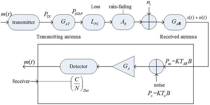
Source: (Alejandro Aragon-Zavala, 2008) [9]
“The performance of a HAPS system is directly related to how high the signal to noise ratio (S/N) at the receiver can be achieved. The received signal power, CRX, is expressed:
Eq. 17-1
CRX = PEIRP x gAR / LFS
Where:
PEIRP = transmitter effective isotropic radiated power, watts,
gAR = receiving antenna gain as a factor,
LFS = free- space loss, as a factor” (Alejandro Aragon-Zavala, 2008)
“The available noise power N, in watts at the input of the ideal amplifier is defined as:
Eq. 17-2
N = k x Ts x B
Where:
N = available noise power, watts
K = Boltzmann’s constant (1.38 x 10 -23 J/K)
B = IF equivalent bandwidth, Hz
Ts = Receiving system noise temperature, Kelvin” (Alejandro Aragon-Zavala, 2008)
And, the receiving noise temperature “Ts is a function of the antenna noise temperature TAR and effective input noise temperature Te, all in degrees Kelvin.” (Alejandro Aragon-Zavala, 2008)
Eq. 17-3
Ts = TAR + Te
Rearranging to get the power to thermal noise:
Eq. 17-4
C / N = PEIRP x g AR[10]
Eq. 17-4 can be expressed in a more convenient format, decibels:
Eq. 17-5
“(C/N) dB = PEIRP – Ls – AR (G /Ts) dB – 10 log (kB)
Where: (G /Ts) dB represents the figure of merit of the receiver, in dB, LFS is the free-space loss, in dB, and PEIRP is the EIRP in dBW.” (Alejandro Aragon-Zavala, 2008)
“A measure of system performance of a digital transmission system is the bit error rate (BER). BER is a function of the energy per bit over thermal noise power spectral density ratio (Eb / No). The latter may be calculated or measured.
The energy per bit is given by:
Eq. 17-6
Eb = C x Tb
Where: C = average power, watts. Tb is the time required to send one bit, secs. It now possible to calculate the carrier-to-noise ratio (C/ N):
Eq. 17-7
(C/N) = Eb /Tb / N0 x B = Eb x R / N0 x B
Where: R = 1 /Tb is the bit rate (b/s)
Playing with Eq. 17-4 we get: (Alejandro Aragon-Zavala, 2008)
Eq. 17-8
Eb / N0 = PEIRP x gAR / k x Ts x R x LFS
The carrier-to-noise spectral density ratio (C/N0) is useful parameter that applies to any one-way RF link. C/N0 in decibels is expressed:
Eq. 17-9
(C/ N0) dB = PEIRP – Ls – AR (G /Ts) dB – 10 log (k x R)
Converting to Eb / N0 is:
Eq. 17-10
(C/ N0) dB = (Eb / N0) dB 10 log (R)
This conversion requires knowledge of the symbol/ bit rate and C/N. “ (Alejandro Aragon-Zavala, 2008) Our primary reference (Alejandro Aragon-Zavala, 2008) gives further equations which define MAR, link margin of error and further manipulate the (Eb / N0) dB. These are left for the student to cogitate. (Alejandro Aragon-Zavala, 2008) on p. 162.
We have reached the key point in our link budget analysis. We can define the uplink (UL) decibel equation from the GTS transmitter to HAPS receiver and the decibel downlink (DL) equation from HAPS transmitter to GTS receiver. These become the working equations.
Uplink equation: [11]
Eq. 17 – 11
(C/ N0) dB, UL = PEIRP, ES – LFS, UL – AR (G /Ts) dB, HAPS, fom, / k – k dB – R dB, UL
Downlink equation:[12]
Eq. 17 – 12
(C/ N0) dB, DL = PEIRP, HAPS – LFS, DL – AR (G /Ts) dB, ES, fom, / k – k dB – R dB, DL
Table 17–7 shows an example “HAPS link budget analysis for Ka -band for clear sky.” (Alejandro Aragon-Zavala, 2008) The primary reference works out many examples at for different bands, weather, elevation angles and other factors. The student is left to explore at leisure.
| Table 17–7 shows an example “HAPS link budget analysis for Ka -band for clear sky.” (Alejandro Aragon-Zavala, 2008) |
|||||
| Parameter | Units | Uplink | Downlink | Uplink | Downlink |
| Elevation Angle | deg | 20 | 90 | ||
| Frequency | GHz | 31.28 | 28 | 31.28 | 28 |
| Bandwidth | MHz | 20 | 20 | 20 | 20 |
| Transmit antenna | |||||
| Power output | dBW | -16.3 | -14.5 | -16.3 | -15.2 |
| Gain | dBi | 35 | 29.5 | 35 | 16.5 |
| EIRP | dBW | 18.7 | 15 | 18.2 | 18.2 |
| Distance | Km | 58.5 | 58.5 | 20 | 20 |
| Free space loss | dB | 157.7 | 156.7 | 148.4 | 147.4 |
| Rain attenuation | dB | 0 | 0 | 0 | 0 |
| Availability | % | 100 | 100 | 100 | 100 |
| Atmospheric gas attenuation | dB | 0.4 | 0.4 | 0 | 0 |
| Receive antenna gain | dBi | 29.5 | 35 | 16.5 | 35 |
| Received power | dBW | -110.9 | -108.1 | -114.2 | -112.2 |
| Noise temperature | K | 700 | 500 | 700 | 500 |
| Interference power density | dBW/MHz | -150.2 | -151.6 | -150.2 | -151.6 |
| Receiver losses | dB | 2.5 | 2.5 | 2.5 | 2.5 |
| Available C/N0 | dB/MHz | 86.3 | 90.6 | 83 | 13.3 |
| Data rate | Mb/s | 13.3 | 13.3 | 13.3 | 13.3 |
| Required Eb/N0,
BER =10 -6 |
dB | 10.5 | 10.5 | 10.5 | 10.5 |
| Coding gain | dB | 5 | 5 | 5 | 5 |
| Obtained
Eb. / N0 |
dB | 5.5 | 5.5 | 5.5 | 5.5 |
| Obtained C/N0 | dB | 76.7 | 76.7 | 76.7 | 76.7 |
| Link Margin | dB | 9.6 | 13.9 | 6.3 | 9.8 |
| Where: | |||||
| Uplink bit rate for elevation angles (UBR) | Mb/s | ||||
| At 20 degrees | Availability % | UBR | At 90 degrees at availability% | UBR | |
| 99.40 | 20 | 20 | |||
| 99.50 | 12.9 | 16.2 | |||
| 99.60 | 7.4 | 12 | |||
| 99.70 | 3.5 | 8.1 | |||
Source: (Alejandro Aragon-Zavala, 2008) pp. 176 -177 [13]
Discussion Questions
HAPS represents so much promise for telecommunications and emergency networking. Researchers have been designing and calculating for three decades. Lots of projects. Lots of money invested. A fascinating technology. But conversion into real projects and utility for the user seems to be still in limbo. Any ideas?
- What stratospheric factors most effect HAPS performance?
- Refer to Table 17 -7. Change the analysis from clear sky to hard rain. What parameters would be affected? Assume the winds have shifted from calm to gale. What parameters would be affected? Shift the frequency to the SHF -band (47 /49 GHz). What would you expect the Link budget analysis to look like?
Bibliography
Adamy, D. (2001). EW 101 A First Course in Electronic Warfare. Boston: Artech House.
Adamy, D. (2004). EW 102 A Second Course in Electronic Warfare. Boston: Artech House.
Adamy, D. (2009). EW 103 Tactical Battlefield Communications Electronic Warfare. Boston: Artech House.
Alejandro Aragon-Zavala, J. L.-R.-P. (2008). High-Altitude Platforms for Wireless Communications. Chichester, West Sussex, UK: John Wiley & Sons.
Brown, E. F. (Dec 2008). Airborne Communication Networks for Small Unmanned Aircraft Systems. Proc. IEEE, vol 96, no 12, pp. 2008-17.
D, G. a. (2010). Broadband Communications via High Altitude Platforms. New York City, NY: John Wiley & Sons.
EARSC. (2015). A Taxonomy for the EO Services Market: enhancing perception and performance of the EO service industry. EARSC Issue 2.
ESA-ESTEC Contract 162372/02/NL/US. (September 2005). STRATOS: Stratospheric Platforms a definition study for ESA Platform, Final Report, 1-34. ESA-ESTEC .
Giordano, N. (2009). College Physics: Reasoning and Relationships. New York City, NY: Cengage Learning. pp. 421–424.
Goddemeir, K. D. (June 2015). Role-based Connectivity Management with Realist Air to Ground Channels for Future Applications. IEEE Vehic. Tech. Mag. Vol 10, no 2, pp. 79-85.
Henderson, T. (2017). The Doppler Effect – Lesson 3, Waves. Physics tutorial. The Physics Classroom. Retrieved from Henderson, T. (2017). “The Doppler Effect – Lesson 3, Waves”. Physics tutorial. The Physics Classroom. Retrieved September 4, 2017.: Henderson, T. (2017). “The Doppler Effect – Lesson 3, Waves”. Physics tutorial. The Physics Classroom. Retrieved September 4, 2017.
Ibrahim, A. (2019). Optimization Methods for User Admissions and Radio Resource Allocation for Multicasting over High Altitude Platforms . Memorial University of Newfoundland , Canada: River Publications.
Jesus Gonzalo, D. L. (2018, March 15). On the Capabilities and Limitations of High Altitude Pseudo-Satellites. Progress In Aerospace Sciences, 37-56. doi:https://doi.org/10.1016/j.paerosci.2018.03.006
Macnamara, T. M. (2010). Introduction to Antenna Placement & Installation. New York City, NY : John Wiley & Sons.
Matolak, R. S. (April 2015). Initial Results for Airframe Shadowing in L-band and C-band Air -Ground Channels. Proc. Integrated Commun,, Navigation, and Surveillance Conf, (pp. pp. 1-8).
Mohorcic, D. G. (2010). Broadband Communications via High Altitude Platforms. New York City, NY: John Wiley & Sons.
Osseiran, A. (Dec 2014). Scenarios for 5G Mobile and Wireless communications: the vision of the METIS Project. IEEE Communications Magazine, Vol 52, no 5, pp. 26-35.
Possel, M. (2017). Waves, motion and frequency: the Doppler effect. Einstein Online, Vol. 5. Max Planck Institute for Gravitational Physics, Potsdam, Germany.
Randall K. Nichols, J. J. (2018). Unmanned Aircraft Systems (UAS) in the Cyber Domain: Protecting USA’s Advanced Air Assets. Manhattan, KS: New Prairie Press.
Rappaport, T. (2014). Millimeter Wave Wireless Communications. New York City, NY: Prentice Hall.
Romano, G. (2017, October 5). Preparing the Ground for IMT-2000. Retrieved from 3gpp.org/news-events/: https://www.3gpp.org/news-events/3gpp-news/1901-imt2020_news
Staff. (2008). FINAL ACTS WRC-07. World Radiocommunication Conference. Geneva: ITU.
Staff. (2012). FINAL ACTS WRC-12. World Radiocommunication Conference. Geneva: ITU.
Staff. (2019). FINAL ACTS WRC-15. World Radiocommunication Conference. Geneva.
Sun, W. M. (June 2015). Unmanned Aircraft Systems:Air-Ground Channel Characterization for future applications. IEEE Vehic. Tech Mag. Vol 10, No 2 , pp. 79-85.
T.C. Dozer, D. A. (2008). High Altitude Platforms for VHDR in-theater communications. IET Seminar on Military Satellite Communications Systems.
Xiaoyang Liu, C. L. (2016). High Altitude Platform Station Network and Channel Modeling Performance Analysis. Mathematics and Computer Science. Vol. 1, No 1, pp. 10-16. doi:Xiaoyang Liu, Chao Liu, Wanping Liu, Xiaoping Zeng. High Altitude Platform Station Network and Channel Modeling Performance Analys10.11648/j.mcs.20160101.13
Zeng, R. Z. (May 2016.). Wireless communications with unmanned aerial vehicles: opportunities and challenges. IEEE Communications Magazine.vol. 54, no.5, pp. 36-42.
Yong Zeng, R. Z. (2016). Wireless Communications with Unmanned Aerial Vehicles: Opportunities and Challenges. IEEE Communications Magazine, 36-42.
- In 2019, there are only five companies in the world offering 5G radio hardware and 5G systems for carriers: Huawei, ZTE, Nokia, Samsung, and Ericsson. In April 2019, the Global Mobile Suppliers Association had identified 224 operators in 88 countries that are actively investing in 5G. (Romano, 2017) ↵
- Only in this chapter is the designation “UAV” used interchangeably with “UAS.” ↵
- A fifth type is ATC (Air Traffic Control) links within a controlled airspace or near an airport. (Yong Zeng, 2016) ↵
- “The stochastic Rician fading model consists of a deterministic LOS component with certain statistical distribution properties. Depending on the environment surrounding the ground terminals and frequency, the UAV-ground channels exhibit widely varying Rician factors – i.e. Power ratio between LOS and the scattered components. Typical values are 15 dB for L-band and 28 dB for C band in hilly terrain. “ (Yong Zeng, 2016) “Rician factors and typical values may be found in Chapter 3 reference” (Alejandro Aragon-Zavala, 2008). ↵
- The author has always been fascinated by the Doppler effect. Henderson gives a decent description of the shift (effect). (Henderson, T., 2017). “The Doppler effect (or the Doppler shift) is the change in frequency or wavelength of a wave in relation to an observer who is moving relative to the wave source. It is named after the Austrian physicist Christian Doppler, who described the phenomenon in 1842. A common example of Doppler shift is the change of pitch heard when a vehicle sounding a horn approaches and recedes from an observer. Compared to the emitted frequency, the received frequency is higher during the approach, identical at the instant of passing by, and lower during the recession. The reason for the Doppler effect is that when the source of the waves is moving towards the observer, each successive wave crest is emitted from a position closer to the observer than the crest of the previous wave. " (Henderson, T., 2017). “Therefore, each wave takes slightly less time to reach the observer than the previous wave. Hence, the time between the arrival of successive wave crests at the observer is reduced, causing an increase in the frequency. While they are traveling, the distance between successive wave fronts is reduced, so the waves bunch together. Conversely, if the source of waves is moving away from the observer, each wave is emitted from a position farther from the observer than the previous wave, so the arrival time between successive waves is increased, reducing the frequency. The distance between successive wave fronts is then increased, so the waves spread out.” (Henderson, T., 2017). ↵
- The author has reviewed / researched a wide variety of books, papers and conference proceedings to build this chapter. The author has chosen as a primary reference (Alejandro Aragon-Zavala, 2008) because of its clarity in terms of student preparation and best “bang for the buck”. Two other newer references are worth mentioning only if your wallet is unlimited: Ibrahim’s Optimization Methods for User Admissions and Radio Resource Allocation for Multicasting over High Altitude Platforms (Ibrahim, 2019) and Grace’s Broadband Communications via High Altitude Platforms (Mohorcic, 2010) ↵
- “The author recommends UAVs for this issue alone. He disagrees with the aerostatic platforms recommended by Stratos project. (ESA-ESTEC Contract 162372/02/NL/US, September 2005)” (Alejandro Aragon-Zavala, 2008) ↵
- “Decibel mathematics is used to compare values that differ in many orders of magnitude. Any number N can be expressed in decibels (dB) is a logarithm base 10. To multiply linear numbers, we add their logarithms base 10. To divide linear numbers, subtract their logarithms base 10. To raise a number to the nth power, we multiply its logarithm base 10 by N. To take the nth root of linear number, we divide its logarithm by N. It is desirable to handle all link budget calculations as early as possible in decibels. To convert the linear number N to decibels:N(dB) = 10 log 10 (N). to convert dB to a linear number we use the relation N = 10 N (dB/10). “Adamy (Adamy, EW 101 A First Course in Electronic Warfare, 2001) Nichols (Randall K. Nichols, 2018) gives examples. “dB equations normally take the form of one of these equations: 1) A(dBm) /_ B(dB) = C(dBm); 2) A(dBm) -B(dBm) = C(dB) and 3) A(dB) = B(dB) /_ N log where N is a number not in dB. Remember that any value in decibels is a RATIO converted to a logarithm. The denominator is usually a known reference base number or value.” (Adamy, EW 101 A First Course in Electronic Warfare, 2001) ↵
- GAR = Gain of receiver. Nomenclature corrected by author. Original paper showed GAT which is the transmit antenna. This would represent the two antenna gains as equal which is unlikely and not a robust solution ↵
- / k x Ts x B x LFS
In (Alejandro Aragon-Zavala, 2008), receiver gain term, gAR is represented at the receiver as g RX without difference of value. ↵
- Nomenclature: ES = Earth Station, FS = Free space loss in UL; AR = Rain attenuation, fom = figure of merit, R = data rate, dB for HAPS uplink. Rain attenuation valid for frequency above 10 GHz. ↵
- PEIRP, ES is the EIRP for HAPS, FS = Free space loss in DL, fom = figure of merit in DL, ↵
- The (Alejandro Aragon-Zavala, 2008) reference was published in 2008 where the world was enjoying LTE 3G and Intel processors of 4th generation cores. Data rates have risen since then. The world is LTE 5G deployment and on-board computers use 8th gen Intel cores with special ASICs and FPGA hardware. Bit rates obviously much more. However, the author is a believer in not reinventing the wheel. (Alejandro Aragon-Zavala, 2008) represents the best product of about 112 papers and texts written in 2016-2019 and reviewed by the author for student benefit and understanding. The basic principles of Link budget analysis for satellites, weapon systems, and HAPs have not changed that much over the year. Nomenclature has been upgraded but the link balance analysis stays the same. A similar argument can be made for chemical engineering with their material and heat balances or in statics where the forces on a unit are conserved. ↵
