Chapter 14: Exposing UAS Vulnerabilities via Electronic Warfare (EW) and Countering with Low Probability Intercept Signals (LPI)
Student Learning Objectives
In previous chapters, we have studied the EMS, Data-links and cyber-vulnerabilities of UAS. This chapter introduces electronic warfare as a method of overwhelming, destroying, or controlling the information, transmitted by communication data-links, to alter the mission of the UAS deployment.
Modern Communication Threats to UAS
Unmanned Aerial Systems (UAS) are in widespread use for reconnaissance, EW, and weapons delivery. They are extremely dependent on interconnection with ground stations by command and data links. (Adamy D. , 2001) The increased use of Low Probability Intercept (LPI) [Introduced in Chapter 13 Data – Links Functions, Attributes, and Latency] has become a significant challenge to electronic warfare (EW) communication links. (Adamy D., 2001) This chapter explores LPI and Jamming, after a circuitous route through Intelligence / Information Operations (IO), followed by EW. The student should then have enough background to understand the criticality of LPI and Jamming of UAS communication links. Air defense missiles and associated radars make significant use of interconnecting links. (Adamy D. , 2001) SUAS sometimes use cellphones to command and control the UAVs. Cell phones are widely used for command and control function in nonsymmetrical warfare situations. (Adamy D. , 2001) ISIS and other terrorist groups use cell phones to trigger improvised explosive devices.
Cybersecurity attacks on data communications links are highly classified. Similarly, modern radar threats to hostile installations are also generally classified. So, in this chapter, description of EW techniques is generalized; no classified information. This way if the student must apply EW in real-world situations, they can plug in the parameters learned from classified sources. Before examining LPI and communications signals/link- jamming, we first review the EW environment specific to UAS.
Definitions
Nichols (2000) defines Cybersecurity in terms of cyber-conflict. (Nichols, 2008) Alford (2000) authored effective definitions for the DoD. These will illustrate the bigger picture of Information Operations (IO) and the subset known as Electronic Warfare (EW).
Cybersecurity (in the context of Cyber conflict) is defined as, “the broad tree of investigation and practice devoted to cybercrimes, Computer Forensics (CF), Information Assurance (IA), Information Security (INFOSEC), Communications Security (COMSEC), and especially Cyber Counter Intelligence (CCI).” (Nichols, 2008)[1]
“Cyber Warfare (CW / CyW). Any act intended to compel an opponent to fulfill our national will, executed against the software controlling processes within an opponent’s system. CyW includes the following modes of cyber-attack; cyber infiltration, cyber manipulation, Cyber assault, and cyber raid.” (DAU, 2018) (DAU, 2018)
“Cyber Infiltration (CI / CyI). Penetration of the defenses of a software-controlled system such that the system can be compromised, disabled, manipulated, assaulted, or raided.” (DAU, 2018) (DoD, 2018)
“Cyber Manipulation (CM / CyM). Following infiltration, the control of a system via its software which leaves the system intact, then uses the capabilities of the system to do damage.
For example, using an electric utility’s software to turn off power.” (DAU, 2018) (DoD, 2018)
“Cyber Assault (CA / CyA). Following infiltration, the destruction of software and data in the system, or attack that compromises system capabilities.” (Alford, 2000) Includes viruses and system overloads via e-mail (e-mail overflow).” (DoD, 2018; DoD, 2018)
“Cyber Raid (CR / CyR). Following infiltration, the manipulation or acquisition of data within the system, which leaves the system intact, results in transfer, destruction, or alteration of data. For example, stealing e-mail or taking password lists from a mail server.” (DAU, 2018) (DoD, 2018)
Cyber-Attack. See CyI, CyM, CyA, or CyR.
Cybercrime (CC / CyC). Cyber-attacks without the intent to affect national security or to further operations against national security.” (Alford, 2000)
“C4ISR. The concept of Command, Control, Communications, Computers, Intelligence, Surveillance and Reconnaissance.” (DoD, 2018) (Kaye, 2001) See Figure 14-XXX (C4ISystems, 2013)
Electronic Warfare (EW) is defined as the art and science of preserving the use of the Electromagnetic Spectrum (EMS) for friendly use, while denying its use by the enemy. (Adamy D. , 2001)
“Information Assurance (IA). Measures that protect and defend information and information systems by ensuring their availability, integrity, authentication, confidentiality, and non-repudiation. These measures include providing for restoration of information systems by incorporating protection, detection, and reaction capabilities.” (Barker, 2003) (Kaye, 2001)
“Information Operations (IO). The integrated employment of the core capabilities of electronic warfare, computer network operations, psychological operations, military deception, and operations security, in concert with specified supporting and related capabilities, to influence, disrupt, corrupt, or usurp adversarial human and automated decision-making process, information, and information systems while protecting our own.” (Barker, 2003) (Kaye, 2001)
“Information Superiority (IS). The capability to collect, process, and disseminate an uninterrupted flow of information while exploiting or denying an adversary’s ability to do the same. A newer form of this is that: degree of dominance in the information domain which permits the conduct of operations without effective opposition.” (Alford, 2000) (Kaye, 2001)
“Information Warfare (IW). Information operations conducted during time of crisis or conflict to achieve or promote specific objectives over a specific adversary. IW is any action to Deny, Exploit, Corrupt or Destroy the enemy’s information and its functions, protecting those actions and exploiting our own military information functions.” (Alford, 2000) (Kaye, 2001)
“Intentional Cyber Warfare Attack (ICWA). any attack through cyber-means to intentionally affect national security (cyber warfare) or to further operations against national security.
Includes cyber-attacks by unintentional actors prompted by intentional actors. (Also see “unintentional cyber warfare attack.”) IA can be equated to warfare; it is national policy at the level of warfare. Unintentional Attack(UA) is basically crime. UA may be committed by a bungling hacker or a professional cybercriminal, but the intent is self-serving and not to further a national objective. This does not mean unintentional attacks cannot affect policy or have devastating effects.
Intentional Cyber Actors (I-actors). Individuals intentionally prosecuting cyber warfare (cyber operators, cyber troops, cyber warriors, cyber forces).” (Alford, 2000)
“Network Centric Operations (NCO). NCO involves the development and employment of mission critical packages that are the embodiment of the tenets of Network Centric Warfare (NCW) in operations across the full mission spectrum. These tenets state that a robustly networked force improves information sharing and collaboration, which enhances the quality of information, the quality of awareness, and improves shared situational awareness. This results in enhanced collaboration and enables self-synchronization improving sustainability and increasing speed of command, which ultimately result in dramatically increased mission effectiveness. (Kaye, 2001)” (MORS, 2018) (Kaye, 2001)
OPSEC. (Operations Security) (DoD-01, 2018) “Determining what information is publicly available in the normal course of operations that can be used by a competitor or enemy to its advantage. OPSEC is a common military practice that is also applied to civilian projects such as the development of new products and technologies.
OPSEC – The Official Definition
(From JP 1-02, Department of Defense Dictionary of Military and Associated Terms, www.dtic.mil/doctrine/new_pubs/jp1_02.pdf.) OPerations SECurity (OPSEC) is a process of identifying critical information and subsequently analyzing friendly actions attendant to military operations and other activities to:
- Identify those operations that can be observed by adversary intelligence systems,
- Determine what indicators adversary intelligence systems might obtain that could be interpreted or pieced together to derive critical information in time to be useful to adversaries, and
- Select and execute measures that eliminate or reduce to an acceptable level the vulnerabilities of friendly actions to adversary exploitation.” (DoD-01, 2018)
“Psychological Operations (PO) Planned operations to convey selected information and indicators to foreign audiences to influence their emotions, motives, objective reasoning, and ultimately the behavior of foreign entities.” (Alford, 2000) (Kaye, 2001)
“Psychological Warfare (PW / PSYWAR) The planned use of propaganda and other psychological actions to influence the opinions, emotions, attitudes and behavior of hostile foreign groups.” (Kaye, 2001)
“Unintentional Cyber Actors (U-actors). Individuals who unintentionally attack, but affect national security and are largely unaware of the international ramifications of their actions. Unintentional actors may be influenced by I-actors, but are unaware they are being manipulated to participate in cyber operations. U-actors include anyone who commits CyI, CyM, CyA, and CyR without the intent to affect national security, or to further operations against national security. This group also includes individuals involved in CyC, journalists, and industrial spies. The threat of journalists and industrial spies against systems including unintentional attacks caused by their CyI efforts should be considered high.
Unintentional Cyber Warfare Attack (UCWA/ UA). Any attack through cyber-means, without the intent to affect national security (cybercrime).” (Alford, 2000)
Information Operations (IO) and the part EW plays
Figure 14-1 shows the global view of Information operations. Note how nicely all the prior definitions fit into the puzzle? Note that EW is a key component of IO, but not the singular dominant puzzle piece. EW “boxes” will be discussed under the EW section below.
Figure 14-2 shows the DoDs JOPES (Joint Operation Planning and Execution System) plan for 2025. In this plan, Information Operations (IO) are integrated across the military commands and equipment / knowledge / software is supplied by both the military and commercial businesses. (DoD-02, 2018)
Figure 14-3 is a look at the DoD Vision of the future of the Internet where IO and IW are gamed into a fully integrated global network system. (Merrick, 2016) All three figures above show how information operations encompasses all the information collection and action activities of the intelligence, defense, military, computer technology, and civilian organizations for common missions of cybersecurity and information superiority. What is not so obvious is that UAS systems are an integral part of IO planning and actions. Further, global investment in the UAS market are growing exponentially and the leader in development is China, not the USA. Much of China’s investment billions are for PLAN which is hostile to USA interests. In Chapters 15 and 16, we address China’s “Grand Strategy” in Africa (a UAS testing ground for several powers) and the Spratly Islands (Intelligence center in the South China Seas).
Figure 14-1 Information Operations
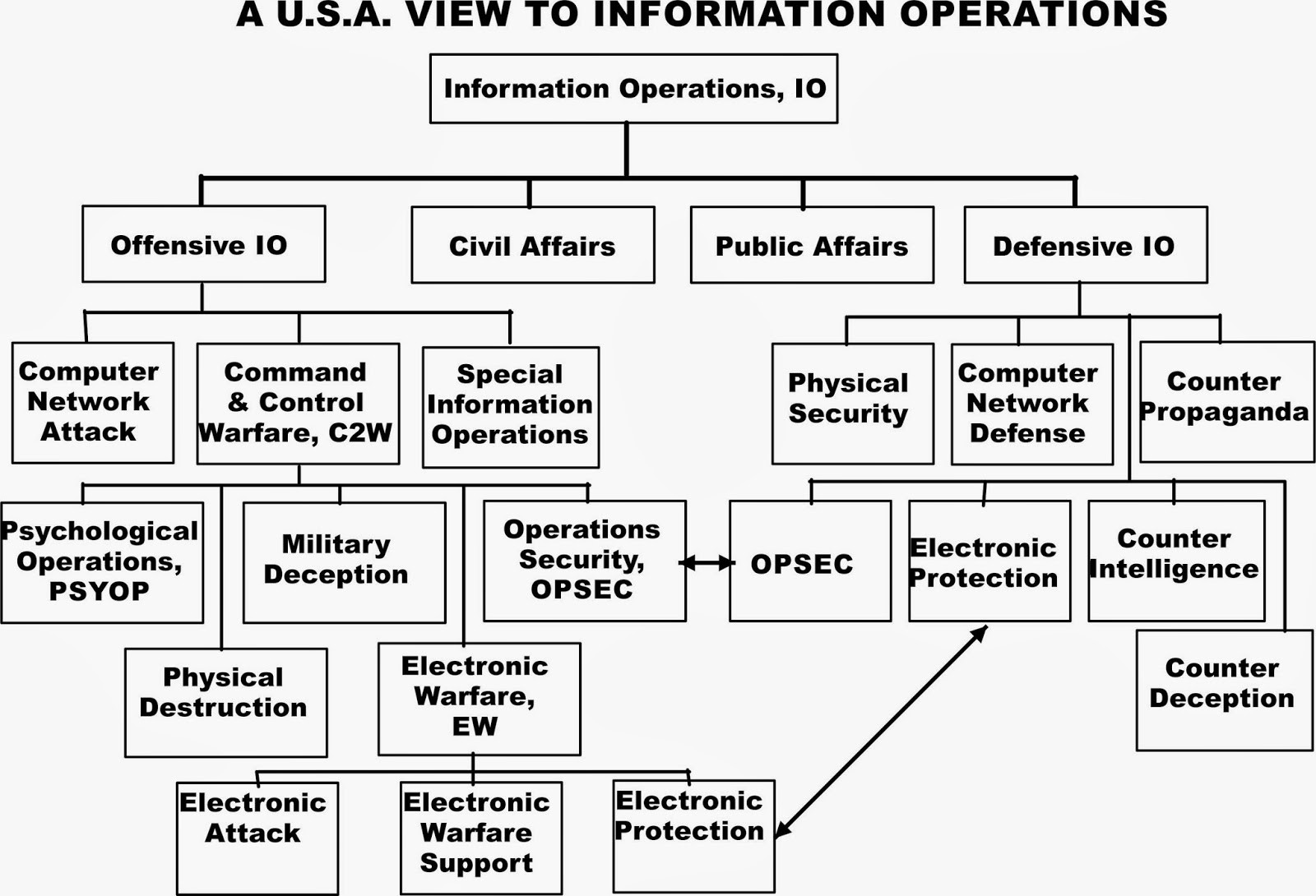
Source: C4ISystems. (2013). Basics-of-information-operations. Retrieved from http://c4isys.blogspot.com/2013/11/basics-of-information-operations-24.html
Figure 14- 2 DoD JOPES
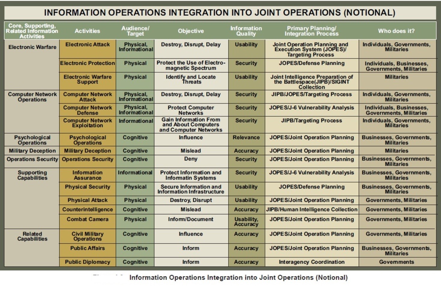
Source: U.S. Department of Defense. Information Operations Integration into Joint Operations (Notional). Viewed on September 1, 2018. Retrieved from https://en.wikipedia.org/wiki/File:IO_Integration_into_Joint_Operations_-_Notional.jpg
Figure 14-3 DoD Vision: Future of Internet with IW / IO integration
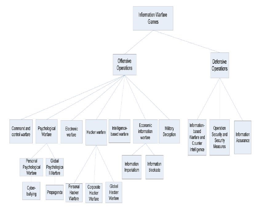
Source: Merrick, K. (2016). Future Internet. 10.3390/fi8030034 Review, 8(3), p. 34.
Electronic Warfare (EW) Purview
Adamy sets the standards for EW instruction. Moir summarizes the topic with respect to military operations, UAS, and military avionics systems. (Moir, 2006) (Toomay, 1982) and (Burch, 2015) bring Radar to the non-specialist reader. A Google search on the key = RADAR yields 296,000,000 results (0.49 seconds). There is substantial material on the subject. The challenge is determining the UAS applicability.
Warfare is conducted by adversaries who go to great pains to understand their enemy’s intentions, strengths, weaknesses, and to minimize the threats to their own forces and territory.
The detection and interception of messages/data, combined with ground observations, provide an ability to observe troop movements and facilitate counter-actions by opposing forces.
As communication developed (satellite, MW, IR, Cell, Radars) so did the methods of interception. Radar started as a simple detection mechanism and grew into a means of surveillance and guidance. (Moir, 2006)
Communication Links for UAS are critical and must be secured
Modern warfare is conducted in a rich electromagnetic environment with radio communications and radar signals from many sources. Unmanned aircraft systems (UAS) / UAV / UUV / Drones are an integral part of modern warfare. UAS communications networks and links to ground stations are critical to the successful military use of UAS. Securing UAS links from EW attacks is a fundamental concern to military planners and civilian authorities. The USMC takes UAS contributions to its Close Air Support (CAS) military planning. Figure 14-4 shows USMC PCAS Vision; precise, digital, portable air-ground strike coordination.[2] This scenario is part of the USMC Guardian Angel program.[3] In September 2016, the Commandant of the Marine Corps, stated the importance of UAS in the USMC battle plans of the future:
“Marine Corps must: develop layers of persistent, armed, multi-spectral, and beyond-line-of-sight (BLOS) UAS above our units to produce responsive intelligence and targeting information, extend our command and control (C2) across a shifting battlespace, and deliver non-kinetic and kinetic fires in support of MAGTF operations.”[4]
UAS BLOS communications require stable communications. Disrupting these communications links is a goal of hostile forces.
Figure 14-4 PCAS Vision: precise, digital, portable air-ground strike coordination
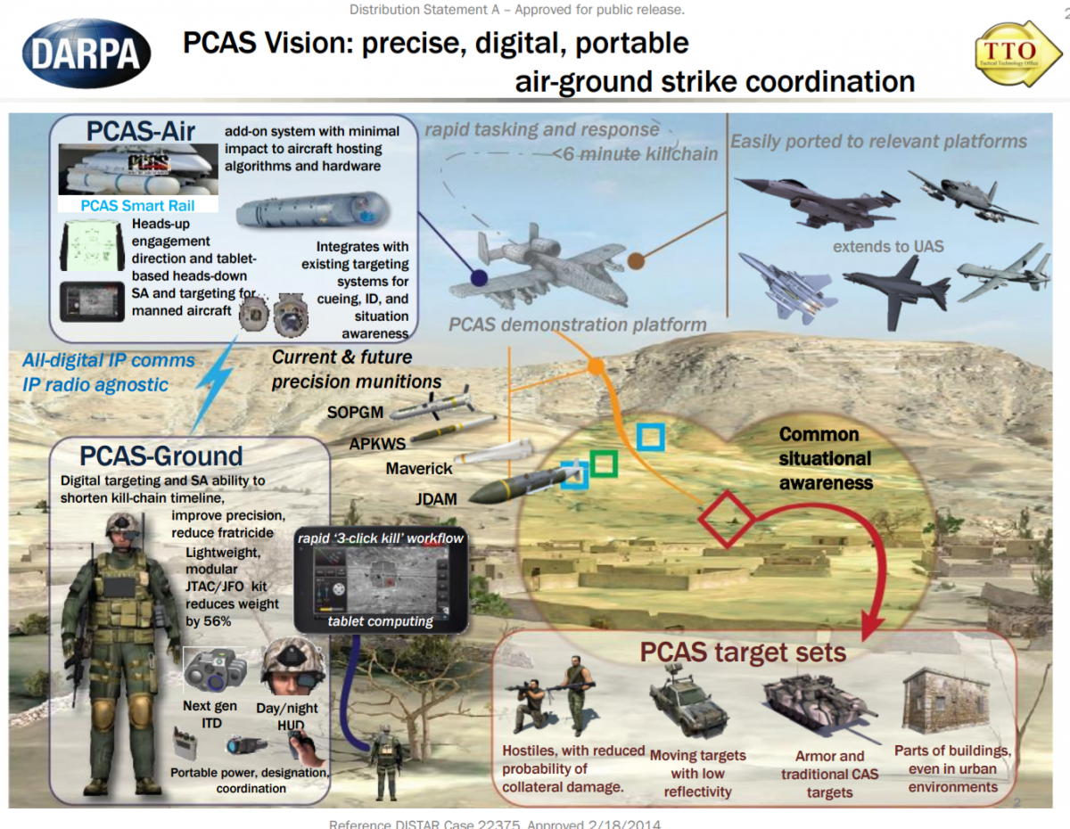
Source: Cuomo, S. (September 2017). “Guardian Angel” UAS, Marine Corps Gazette, 101(9). https://www.mca-marines.org/gazette/guardian-angel-uas
DoD has also made plans to build UAS into its mission.
Figure 14-5 shows a complex operational concept to be executed over the next twenty years. (DoD-03, 2015) Think of the designers’ struggles to meet required future communication links to the UAS.
Figure 14-5 High -Level C4 Operational Concept Incorporating UAS
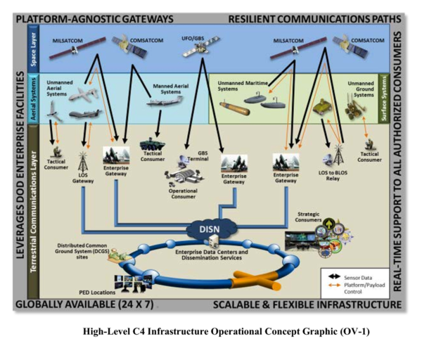
Source: (DoD-03, 2015) DoD-03. (2015). Unmanned Systems Roadmap 2013 to 2038. Retrieved from DTIC: http://www.dtic.mil/dtic/tr/fulltext/u2/a592015.pdf
Figure 14-6 shows NASA’s Unmanned Aircraft Systems (UAS) Integration in the National Airspace System (NAS) Project (2018). All communications are in real-time. (NASA, 2018)
Figure 14-6 NASA’s Unmanned Aircraft Systems (UAS) Integration in the National Airspace System (NAS) Project (2018)
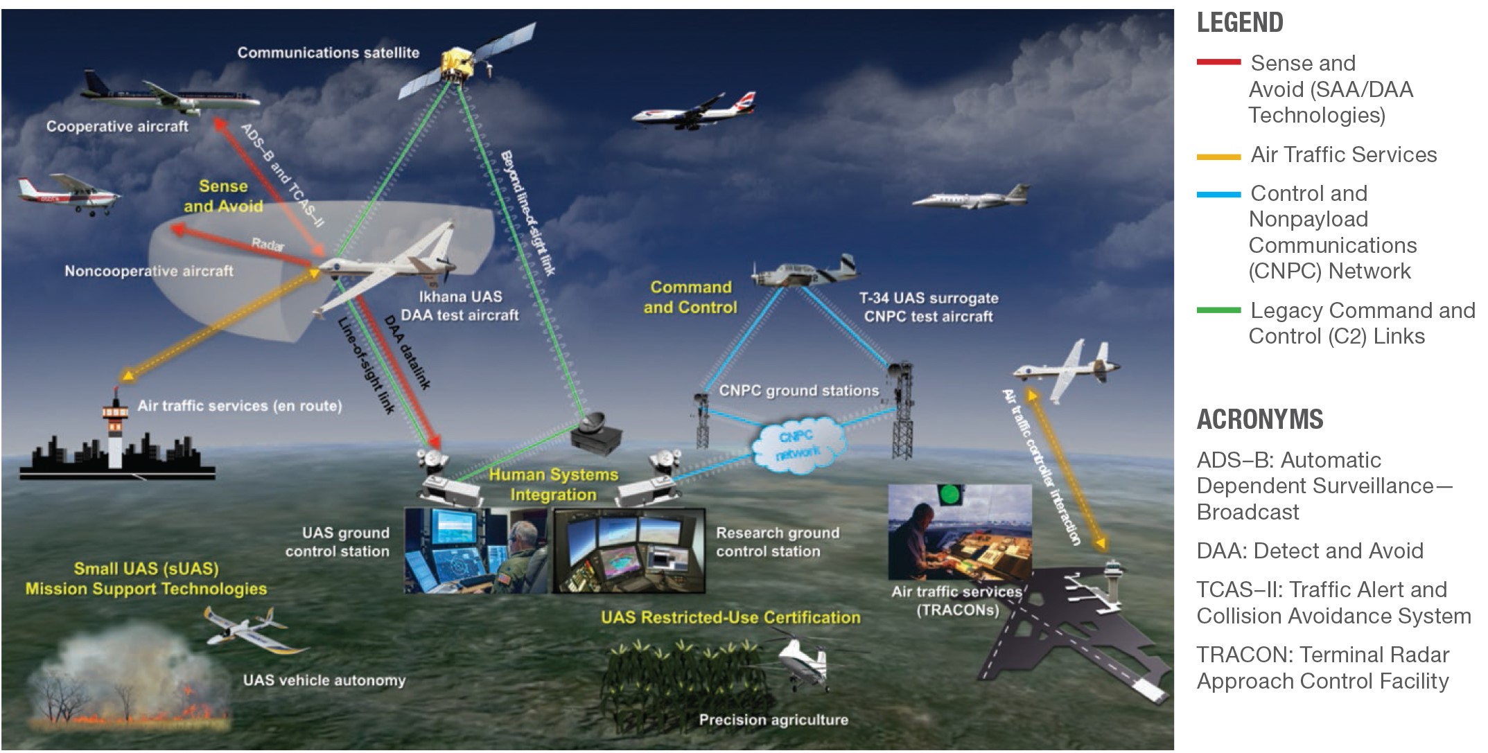
Source: NASA. (July 28, 2018). NASA Unmanned Aircraft Systems (UAS) Integration in the National Airspace System (NAS) Project. https://www.nasa.gov/feature/autonomous-systems DLA 07282018
In a theater-wide scenario, with combined land, sea, and air forces operating against enemy territory, which in turn, are defended with similar forces, we can envision multiple roles for UAS. These include military planning, air defenses, air superiority aircraft, defense suppression, HVT assassination,[5] maritime operations, offensive operations, naval forces, land forces, cyber forces, TV reporters, mobile telephone traffic, and sound satellite links. (Moir, 2006) The radio frequency spectrum (and EMS) covered by emitters used by the forces is broad as was illustrated in Figures 8-1, 8-3, 13-4 and Table 13-1. No single transmitter /receiver can cover this range for transmission or reception. Most communications and radar systems are designed for use in specific bands, designated by international convention. (Moir, 2006) See Figure 8-8 Radio frequency bands and Figure 8-9 Radar frequency bands.
The key role of EW is to search these radio-frequency bands to cull information that can be used for intelligence analysis or by front-line operators. (Moir, 2006) The information gathered may affect a tactical advantage on the battlefield, or in any stage before or after. (Moir, 2006)
Intelligence Cycle
In the CIA, intelligence is viewed as a continuous cycle of activities to keep ahead of adversaries always (peace, transitions, war). Figure 14-7 shows the Intelligence Cycle.
Figure 14-7 Intelligence Cycle
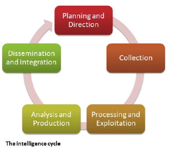
Source: Count upon Security. (August 15, 2015). The Five Steps of the Intelligence Cycle. https://countuponsecurity.com/2015/08/15/the-5-steps-of-the-intelligence-cycle/ DLA 07282018
The cycle begins with a user requesting intelligence be gathered on a scenario. The analysts will develop a set of requirements for the collection stage. Intelligence is then gathered via surveillance platforms; espionage, co-operative exchange, or open source documents. The intelligence is sent to a processing group whereby the data is analyzed, collated, validated, and securely disseminated to the users or to trusted allies. They are read, evaluated, and acted on based on the intelligence. Or the user may rethink the needs/parameters of the project, returning the direction back to a modified intelligence requirements document, which is then transferred over to the collection group, analysis, reporting, and so forth.
EW Generalities
Time to fill in the EW boxes in 14-1. Electronic warfare (EW) is defined as the art and science of preserving the use of the electromagnetic spectrum (EMS) for friendly use while denying its use by the enemy. (Adamy D., 2001) The EMS is from DC to light and beyond. See Figures 8-1 to 8-4 EMS Spectrum views. EW covers the full radio frequency spectrum, the infrared spectrum, and the ultraviolet spectrum.
Legacy EW definitions
EW was classically divided into: (Adamy D., 2001)
- ESM – Electromagnetic Support Measures – the receiving part of EW;
- ECM – Electromagnetic Countermeasures – jamming, chaff, flares used to interfere with operations of radars, military communications and heat-seeking weapons;
- ECCM -Electronic Counter-Counter Measures – measures taken in design or operation of radars or communications systems to counter the effects of ECM.[6]
Not included in the EW definitions were Anti-radiation Weapons (ARW) and Directed Energy Weapons (DEW).
USA and NATO have updated these categories:
- ES – Electronic warfare Support (old ESM)
- EA – Electronic Attack – which is the old ECM but also includes ASW and DE weapons;
- EP – Electronic Protection – (old ECCM) (Adamy D. , 2001)
ES is different from Signal Intelligence (SIGINT). SIGINT is made up of Communications Intelligence (COMINT) and Electronic Intelligence (ELINT). All these fields involve the receiving of enemy transmissions. (Adamy D. , 2001)
COMINT receives enemy communications signals to extract intelligence.
ELINT uses enemy non-communications signals for determining the enemy’s EMS signature so that countermeasures can be developed. ELINT systems collect substantial data over large periods to support detailed analysis.
ES/ESM collects enemy signals, either communication or non-communication, with the object to do something immediately about those signals or the weapons associated with those signals. The received signals might be jammed or the information sent to a lethal responder. Received signals can be used to type and locate the enemy’s transmitter, locate enemy forces, weapons, distribution, and electronic capability. (Adamy D. , 2001)
Adamy (2001) is correct when he suggests that the, “key to understanding EW principles (particularly the RF) part is to understand radio propagation theory. Understanding propagation leads logically to understanding how they are intercepted, jammed or protected.” (Adamy D. , 2001) Adamy has written five books and published numerous papers on the subject. The student can explore his works or use (Moir, 2006) or (Toomay, 1982) (light reading and dated text to dive into RF propagation.) Petti’s book on ECCM is simplistic but has legacy views of the EP function. (Pettit, 1982) One of the classics that should read is by Lt. Col. USAF Fitts, The Strategy of Electromagnetic Conflict (Fitts, 1980) Lastly, a decent text on ELINT beginnings is authored by Wiley. (Wiley, 1993)
Main Contention
It is the author’s contention that UAS communication links are vulnerable and must be evaluated to protect US Unmanned Aircraft in the cyber or electronic domain. Further, those links may be electronically jammed, cyber-spoofed (especially navigational), or made ineffective with electronic or cyber interference.[7]
Cyber-spoofing is conjectured in Chapter 16 in the GPS cyber-spoof discussion of the Spratly Island complex, Red Drones, and US Capital ships colliding with commercial vessels. The remainder of this chapter will focus on the electronic jamming, LPI countermeasures and UAS vulnerabilities to electronic interference.
Communications Jamming
The purpose of communication is to move information from one location to another. All the following types of transmitted signals are communications:
- “Voice or non-voice communications (video or digital format)”;
- “Command signals to control remotely located assets;”
- “Data returned from remotely located equipment”;
- “Location and motion of friendly or enemy assets (land, sea, or air);”
- UAS communications links from it ground station for control of the aircraft;
- UAS communications links from another aircraft or satellite affecting its flying characteristics;
- UAS communication signals (from any source) that affect the SAA / navigation / payload / waypoints;
- Computer-to-computer communications;
- Data links;
- Weapon-firing links;
- ISR data links;
- Cell phones. (Adamy D., 2009)
“The purpose of communications jamming is to prevent the transfer of information. Communications jamming requirements depend on the signal modulation (strength), the geometry of the link, and the transmitted power.” (Adamy D., 2009) Another way to think of jamming is a method to “interfere with the enemy’s use of the electromagnetic spectrum. Use of EMS involves the transmission of information from one point to another”. (Adamy D., 2009)
“The basic technique of jamming is to add an interfering signal,” along with the desired signal, into an enemy’s receiver. “Jamming becomes effective when the interfering signal is strong enough to overwhelm the desired signal.” This prevents the enemy from recovering the information from the desired signal. (Adamy D., 2009) There are two possible methods for a successful jam: either the jamming signal is stronger than the desired “signal or the combined signals received have characteristics that prevented the processor from properly extracting the desired information.” (Adamy D., 2009) A simple case of jamming unintentionally is when your AM news station (listening in the car) becomes overwhelmed by junk music. You can hear the beginning of the interference as noise, then the junk signal is strong, then as the car moves out of the area, the AM news station regains its status. (Adamy D., 2009)
The cardinal rule of jamming is that you jam the receiver, NOT the transmitter. (Adamy D., 2001)
Figure 14-8 shows the communication jamming geometry. (Adamy D., 2009)
“The primary difference between radar and communication jamming is in the geometry. Whereas a typical radar has both the transmitter and the associated receiver at the same location, a communication link, because its job is to take information from one location to another, always has its receiver in a different location from that of the transmitter.” (Adamy D. L., 2004)
In Figure 14-8, the “communications-jamming geometry has one-way links from the desired transmitter and the jammer to the receiver.” (Adamy D. L., 2004)
Figure 14-8 shows the communication jamming geometry

Source: Adamy, D. (2009). EW 103 Tactical Battlefield Communications Electronic Warfare. Boston, MA: Artech House.
“Communication is often done using transceivers (each including both transmitter and receiver), but only the receiver at location B in the figure is jammed. If transceivers are in use and one desires to jam the link in the other direction, the jamming signal must reach location A.” (Adamy D. L., 2004)
“There are some important communications instances in which transceivers are not used. For example, in UAV links as shown in Figure 14-9, this figure shows the data link (or “downlink”) being jammed. Again, the receiver is the objective to be jammed.” (Adamy D., 2009)
Figure 14- 9 UAV Link Jamming Geometry
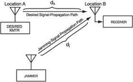
Source: Adamy, D. L. (2004). EW 102 A Second Course in Electronic Warfare. Boston: Artech House. Also see: https://www.globalspec.com/reference/61136/203279/5-8-communications-jamming
“Figure 14-9 shows that a jammer operating against a UAV data-link must target the receiver at the ground station.
Another difference of radar jamming is that the radar signal makes a round trip to the target, so the received signal power is below the transmitted power by the fourth power of the distance (often stated as 40 log range). Since the jammer power is transmitted one way, it is only reduced by the square of distance.” (Adamy D. L., 2004)
Table 14-1 shows the Types of Jamming. (Adamy D., 2001)
| Type of Jamming | Purpose |
| Communications jamming | “Interferes with enemy ability to pass information over a communication link” |
| Radar jamming | “Causes radar to fail to acquire its target, to stop tracking target, or to output false information” |
| Cpver jamming | “Reduces the quality of the desired signal so that it cannot be properly processed, or the info is lost / unrecoverable” |
| Deceptive jamming
|
“Causes radar to improperly process its return signal to indicate the correct range or angle to target” |
| Decoy | “Looks like the target more than the actual target; causes a guided weapon to attack the decoy rather than intended target.” |
Table 14-1 Types of Jamming
Source: (Adamy D., 2001)
To be effective, the jammer must get its signal into the enemy’s receiver – through the associated antenna, input filters, and processing gates. This depends on the signal strength the jammer transmits in the direction of the receiver and the distance and propagation conditions between the jammer and the receiver. (Adamy D., 2009)
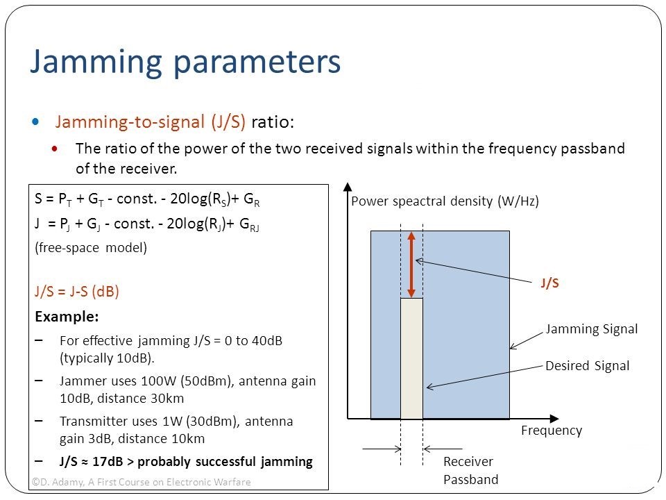
Jammer-to-Signal Ratio
The real test of jammer effectiveness is the effectiveness with which information flow is stopped. “A jammer interferes with communication by injecting an undesired signal into the target, receiver along with any desired signals that are being received.” (Adamy D. , 2009) “The obstructing signal must be strong enough that the receiver cannot recover the required information from the desired signals.” The ratio of the jamming signal to the desired signal is known as the jamming–to-signal ratio (J/S), stated in dB.[8] Effective J/S depends on the transmitted modulation, but the Adamy formula works in general. (Adamy D., 2001)
Refer to Figure 14-9 UAV Link Jamming Geometry. The jammer-to-receiving link and the desired transmitter-to-receiver UAV link in Figure 14-9 can employ any propagation model. (Adamy D., 2009)
“The formula for communication J/S is:
Eq. 14-1
J / S = ERPJ – ERPS – LJ + LS + G RJ – G R
Where: J/S = the ratio of the jammer power to the desired signal power at the input to the receiver being jammed in dB
ERPJ the effective radiated power of the jammer in dBm
ERPS the effective radiated power of the desired signal transmitter, in dBm
LJ the propagation loss from jammer to receiver, in dBi[9]
LS The propagation loss from the desired signal transmitter, in dBm
GRJ the receiving antenna gain in the direction of the jammer, in dBi
GR The receiving antenna gain in the direction of the desired signal transmitter, in dBi.” (Adamy D., 2001)
Many UAS (especially UAV or sUAS ) have a target receiving antenna with a 360-degree azimuth coverage. They use whips or monopoles. They are inexpensive. With a 360-degree antenna, the communications J/S equation simplifies to:
Eq. 14-2
J / S = ERPJ – ERPS – LJ + LS
The receiving antenna has the same gain toward the jammer and the desired signal transmitter. The two gain terms cancel out. (Adamy D., 2009)
Figure 14-9 shows a simple example where the J /S calculation would indicate a successful jam (desired signal fully compromised). (Adamy D., 2001) The terminology is slightly different for the power terms (removing the “effective radiated” and using “power total” instead). The principle is still the same. (Adamy D., 2009)
US Army Field Manual FM 34-40-7 (23 Nov 1992) Communications Jamming Handbook, presents three alternative methods for calculating the jamming power required and distance to target. For the designer of an anti-UAS Drone gun, which transmits a jammer signal to a UAS to overwhelm the desired ground station command signals, one needs the know the power and height of the drone. Since the drone is moving the jammer signal must radiate in such a manner that it covers a volume of space until target “UAS lock.” Recall Figure 7-5 Drone Jammer Model KWT-FZQ. Table 14-2 shows the details for this anti-drone gun.[10]
Figure 14- 10 J/S Calculation Example
Source: Cagalj, M. (2014). FELK 19: Security of Wireless Networks: University of Spain PPTX Presentation.
Quote from manufacturer Globaldroneuav.com: (Adamy D. , 2009)
“Anti-drone rifle is multiband device which sends a high-power electromagnetic wave that is used to interfere with UAV flight and force the remote low-altitude drone to drop, fly to home place or to land stably. By triggering the rifle, it disturbs the GPS location and breaks the video transmission control link of UAV instantly to achieve the effective control of “Unapproved fly.” It’s a portable gun all-in-one design with robust strength and fast use features make its easy start by one triggering after battery assembly. Multi antennas and multi-bands frequency works simultaneous in the front end of gun, which enables the effective control range more than 1000 meters. The tripod makes longtime watching much easier, which facilitates it popular in such no-fly zones as airport, prison and military areas and so on. What is more, it is very convenient to guarantee the activities going safely and orderly in the important security areas and urban management sites.”
Table 14-2 Tri-band Anti Drone Rifle KWT-FZQ/DG10-A[11]
Functions and features
1. Full range cover within three frequency section and high-power transmission helps to achieve the ideal effects.
2. Fast trigger, easy use and daughter switch design make control more ease and comfort.
3. Dual lithium batteries for power supply last work time longer.
4. The strong internal line connector and external fuses port make the whole vehicle and component parts fastened securely.
5. All aluminum alloy case body design and glass fiber material for antenna cover make its appearance lighter and faster.
| Technical parameters |
|||
| SN | Parameter name: | Parameter index record: | |
| 1 | Power supply | Work voltage V | DC13V~16.8V |
| 2 | Work current A | ≤9A@DC14.8V | |
| 3 | Work time | ≥1.5h | |
| 4 | Radio Frequency | Work frequency range MHz | (1550±5) MHz~(1620±5)MHz
(2400±5) MHz~(2483±5)MHz (5725±5) MHz~(5852±5)MHz |
| 5 | 40dBm@1550~1620MHz(±1dB) | ||
| 6 | Output power dBm | 37dBm@2400~2483MHz(±1dB) | |
| 7 | 37dBm@5725~5852MHz(±1dB) | ||
| 8 | Out of band rejection | <-36dBm@30~1000MHz
<-30dBm@≥1GHz |
|
| 9 | Specification & environment |
Weight | 4.8kg±0.2kg(Mainframe +battery)
0.6kg±0.1kg(sighting telescope) |
| 10 | Dimension | 1323mm×403mm×341 mm, with battery and antenna | |
| 11 | Work environment humidity | ≥95% | |
| 12 | Work temperature | -25℃~55℃ | |
| 13 | Storage temperature | -40℃~70℃ | |
Appearance dimension :(mm)L×W×H;
1323mm×403mm×341 mm
Weight(Kg):4.7kg±0.2kg(mainframe + battery)
0.6kg±0.1kg(sighting telescope)
Source: Tri-band Anti Drone Rifle KWT-FZQ/DG10-A Manufacturer: Globaldroneuav.com https://globaldroneuav.com/Product/Police-drone-jammer-effective-drone-controller.html
Alternative: A Chinese firm makes an anti-drone gun that costs about $35,000 USD and operates on 5.8 GHz and 2.4 GHz.[12] 80% of consumer drones operate on these frequencies. “The gun tricks the drone into thinking it has lost connection with its controller.” “RC signal lost” is flashed on drone screen – aircraft returning to home point.” The drone can be recovered intact. This gun has an operational limit of about 700 meters (0.43496 miles).
Calculating the minimum of “amount of jammer power output required in watts” for this easy drone capture would be of interest. (Army, 1992) FM 34-40-7 Appendix gives a slightly different version of the Adamy equation 14-2:
Eq. 14-3
P j = P t x K x (H t / H j )2 x (D j / D t )N
Where:
“P j = Minimum amount of jammer power output required , in watts
P t = Power output of the enemy drone, in watts
H j = Elevation of the jammer location above sea level, feet
H t = Elevation of enemy transmitter location above sea level, in feet
D j = Jammer location – to-target receiver location distance, in km
D t = Enemy transmitter location -to- target receiver location, in km
K = 2 for jamming frequency modulated receivers (jamming tuner accuracy)
N = Terrain and ground conductivity factors
5 = very rough terrain with poor ground conductivity
4 = Moderately rough terrain with fair to good ground conductivity
3 = Farmland terrain with good ground conductivity
2 = Level terrain with good ground conductivity
F = Frequency in MHz” (Army, 1992)
“Note: The elevation of the jammer location and the enemy transmitter location does not include the height or length of the antenna above the ground. (Army, 1992) It is the location deviation above sea level.
Given the following parameters:
“P j = Minimum amount of jammer power output required , in watts = (SOLVE)
P t = Power output of the enemy transmitter -to drone, in watts = 5 watts
H j = Elevation of the jammer location above sea level, feet, use 385m =.385 km
H t = Elevation of enemy transmitter location above sea level, in feet use 386m =.386 km
D j = Jammer location – to-target receiver location distance, in km = 700 m = 0.700 km
D t = Enemy transmitter location -to- target receiver location, in km = 372m = 0.372 km
K = 2 for jamming frequency modulated receivers (jamming tuner accuracy) = 2
N = Terrain and ground conductivity factor = Use 4 for moderate terrain with fair to good ground conductivity” (Army, 1992)
F = Frequency in MHz, use 37.5 MHz in the band
Parameters were chosen so that the height ratio would drop-out and the distance would induce some ground conductivity effects consistent with the FM 34-40-7 examples.
Plugging the numbers and solving for P
P j = 5 x 2 x (1)2 x (0.7 / 0.372)4 = 10 x (1.88) 4 = 10 x 12.46 = 125 watts
So, under these hypothetical conditions the jammer gun requires 125 watts (2 60-watt light bulbs) to take down the drone. Theoretically, if the jammer was using a log periodic array (LPA) the power could be cut in half to 62.5 watts (1 bulb). Now if this calculation is reasonable, the buyer is spending $35,000 USD to take down a small irritating drone (invasion of privacy) using a 60-watt bulb. A double-aught shotgun shell with a 12-gauge Remington and yellow shooter sunglasses will have the same effect (might even be more satisfying) for 1/100 the cost. The medium size drones present a more interesting case. More power is needed to lock on to the higher altitude UAS. The term of interest in the jamming equation from FM 34-40 -7 is the ratio of the distances to the fourth power (or second power for perfect terrain). That can have a major impact on jammer output power. (Army, 1992)
Radar Range Equation
Equation 14-3 is not the only place we see a term taken to the 4th power. The famous “Radar Range Equation is dominated by the R4 factor in the denominator. There is no corresponding function in the numerator of equation 14-4, with an exponent greater than unity. (Toomay, 1982) There is no magic bullet to achieve a high-performance system. If low cross section targets are to be engaged, a combination of high-power, high gain, large aperture, and low-noise needs to be dictated.” (Toomay, 1982)
See Figure 14-13 Simple Radar Block Diagram for discussion, after a quick history lesson.
Radar is an excellent technology to “see the UAS” coming into defensive space. RADAR is an acronym for “Radio Detection and Ranging.” “Radio waves occupy a small portion of the EMS from frequencies of a few kHz, a few thousand cycles per second, to a few million MHz, over 1012 cycles per second.” (Toomay, 1982) We can thank Heinrich Hertz, who in 1886, conducted “experiments showing that radio waves reflected, refracted, were polarized, interfered with each other, and travelled at high velocity”. The Maxwell equations were confirmed and the properties of “reradiation and of known velocity portended the future of radar.” (Toomay, 1982)
Radio waves were first used for communications, generate by spark gaps generating short intense pulses of current to achieve the needed electromagnetic radiation. The real break-through in radar was by Lee Deforest in 1906. He invented vacuum tubes. Sinusoidal oscillators came next in evolution. [Yes, transistors and mini-transistors came down the line for another revolution, but who cares?] All the ingredients were in place (Valid theory, experiments, and practical transmitters and receivers), but it was Robert Watson Watt in 1930’s, who fielded a radar system in the field. (Toomay, 1982) The English Air Ministry were glad he did so! The WWII air Battle of Briton was won by using Watson’s radar to spot and warn the English fighters as to the German bombers and fighter escorts location, altitude, distribution, and number of planes in the attack.
The Chain-Mall Radar stations (codename Chain Home) were strategically located all along the English Coast. See Figure 14-11. Figure 14-12 shows an example of one of these primitive radar stations. The German High command discounted the radar theory until it was too late in 1943.
Figure 14-11 Chain Home Radar Stations Defending England
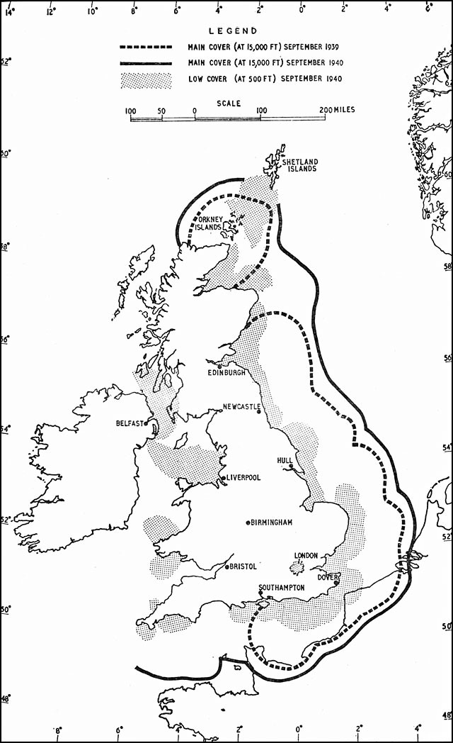
Source: Richards, D. (n.d.). Hyper war: The Royal Air Force 1939-1945, Vol. I: The Fight at Odds. Viewed September 13, 2018, Retrieved from http://www.ibiblio.org/hyperwar/UN/UK/UK-RAF-I/UK-RAF-I-6.html and http://enacademic.com/pictures/enwiki/67/Chain_home_coverage.jpg
Figure 14-12 Chain Home Radar Station
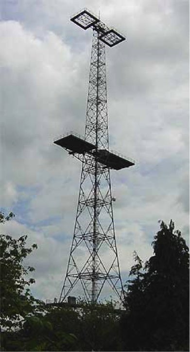
Source: Richards, D (2010). Hyper war: The Royal Air Force 1939-1945, Vol. I: The Fight at Odds. Retrieved from http://enacademic.com/dic.nsf/enwiki/219451/Chain_Home (codename)
“The principles of a primitive radar are formed. Figure 14-13 diagrams its functions. A burst of electromagnetic energy, oscillating at a predetermined frequency is generated and radiates into free space from an antenna. A clock is started. The electromagnetic energy propagates outward at the speed of light, reradiating (scattering) from objects it encounters along its path. Part of the scattered energy returns to the radar (is received) and can be detected there because it imitates the frequency and duration of the transmitted pulse.” (Toomay, 1982) (Figure 14-14)
Figure 14-13 Simple Radar Block Diagram
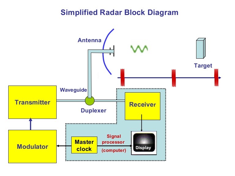
Source: Goel, R. (2014). Simplified Radar Block Diagram https://www.slideshare.net/remotesensor1/radar-transmitter-4-1
A full derivation of all the terms, the radar spherical geometry and derivations of subset equations are in all legacy and modern radar texts and papers.
Figure 14-14 Simple Surveillance Radar
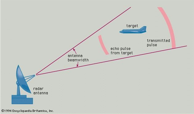
Source: Radar spherical Geometry to target. (1994). In Encyclopedia Britannica. https://www.britannica.com/technology/radar
The standard Radar Range Equation (RRE) is:
Eq. 14-4
S / N = (P GTArσ ) / [(4π)2 R4 KTS LS ]
Where:
S / N = is one pulse received signal to noise ratio, dB
P = Isotropic source of an electromagnetic pulse of peak power, Mw
GT = Gain of the transmit antenna, dB
Ar = Receive antenna effective area, m2
σ = Radar Cross Sectional Area, m2
R4 = Energy density received at detected target range, R, nm
K = Boltzmann’s constant (Noise component)
TS = Measured noise temperature, Kelvin units above absolute zero
LS = Losses existing in the system (lumped together), dB
Inherent in equation 14-14, is the fact that the range of the radar to a “detected object can be calculated by: R = ct / 2, where c is the speed of light (3 x 10⁸ m/s) x time , in sec. also, λ = c / f, where λ is the wavelength in Hz, and frequency, f is the cycles/second for the sinusoidal oscillator.” (Toomay, 1982)
The point of this diversion into Radar history was that the performance of both the jamming equation and the radar range equation are affected by a power of 4th exponent. This affects equipment design, cost, effectiveness of detection or capture.
LPI Communication Signals
The author gave the answer to the question never asked at the beginning of this chapter. The answer was LPI (Low Probability of Intercept) communications presented challenges to EW communication links. (Adamy D. -0., 2015) “They are extremely dependent on interconnection with ground stations by command and data links” And the question was how does the US protect its UAS/UAVs/drones from hostile take-over, considering the vulnerabilities of communication links from ground to UAS platform? Signals associated with LPI communications have unique modulations[13] designed to seriously perturb detection possibilities for the normal types of receivers. (Adamy D. -0., 2015) If designed correctly, a hostile receiver will not even detect the presence of the signal.
This is accomplished by spreading the frequency range over which the LPI signal is broadcast. (Adamy D. -0., 2015)[14] (Figure 14-15)
Figure 14-15 Spread Spectrum Signal
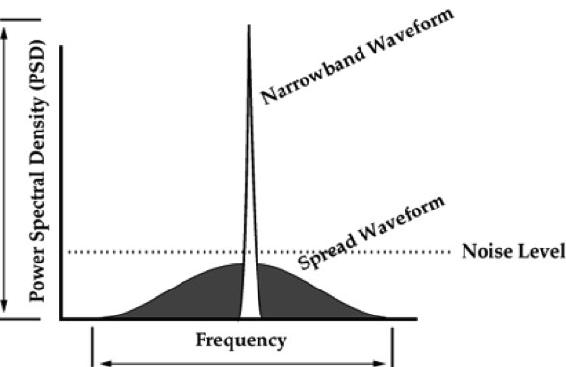
Source: Price, H. (1995). Digital Communications, column, NK6K, from QEX. http://www.qsl.net/n9zia/ss.qexss.html
Figure 14-15 shows the effect of a second modulation applied to the narrowband waveform to spread its frequency over a larger part of the spectrum and reduce the power spectral density to less than random noise. (Adamy D. -0., 2015)
Four types of spreading modulations are used: (Adamy D. -0., 2015)[15]
- Frequency Hopping: The transmitter periodically hops to a pseudo-randomly selected frequency. The range is much greater than the bandwidth of the signal carrying the information to be communicated. (Adamy D. -0., 2015)
- Chirp: The transmitter is rapidly tuned across a frequency range that is significantly wider than the information bandwidth. (Adamy D. -0., 2015)
- Direct Sequence Spread Spectrum (DSSS): The signal is digitized at a rate much higher than required to carry the information. This spreads the energy of the signal across a wide bandwidth. (Adamy D. -0., 2015)
- Complex combinations: Experimental models combining two or more spreading modulations made up of frequency hopping, chirp, and DSSS.
LPI Restrictions
There are several restrictions on the effective use of LPI as a counter EW tactic for UAS.
LPI equipment and software may be cost-ineffective in smaller UAS systems.
- The spreading modulator in the receiver must be synchronized with the spreading modulator in the transmitter to reverse the spreading modulation so that the signal can be returned to the same bandwidth (information bandwidth) it had before the “secrecy operation”;
- The synchronization requires that both the modulator and demodulator use the same pseudo-random function based on same digital code sequence;
- the codes transmitted and received must be in phase; and
- synchronization may require a delay before the transmission begins.
Discussion Questions /Assignment
Chapter 14 concentrated on UAS, EW, and LPI. However, there is a closely related science that intersects with EW and that is Cyber. There are distinct parallels and intersections between Cyber and EW. For instance, the sister of signal spreading techniques is encryption. See Figure 14-16 showing the intersection of Cyber, EW, and Spectrum Warfare designated as Cyber Electromagnetic Activities (CEA)[16] Figure 14-17 puts CEA in the perspective of total war.[17][18]
Student will research CEA and its parallels to EW (start with FM 3 – 38 Cyber Electromagnetic Activities in CANVAS or use Google to find the free PDF) How do these intersections support both friendly and hostile actions on UAS systems in all classes? Develop a PowerPoint presentation with your answers for class submission. Look for tools like cyber offensive weapons against key UAS systems and cyber defensive weapons/countermeasures that can be used to thwart the cyber weapons that you have found in Open Source literature (Non- CLASSIFIED). Try to develop a taxonomy around your findings.
Figure 14-16 Cyber Electromagnetic Activities
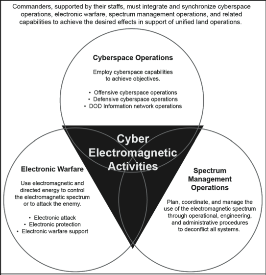
Source: US Army. (2014). FM 3-38 (2014) Cyber Electromagnetic Activities (US Army)
Figure 14-17 CEA / CEW in the view of Total War
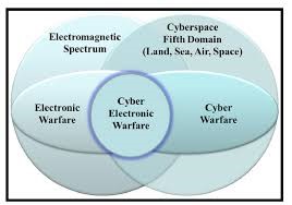
Source: Askin, O., Irmak, R, and Avseyer, M. (14 May 2015). Cyber warfare and electronic warfare integration in the operational environment of the future: cyber electronic warfare. Proceedings Vol 9458, Cyber Sensing 2015; 94580H (2015) SPIE Defense + Security, 2015, Baltimore, MD. https://doi.org/10.1117/12.2189351
Bibliography
Adamy, D. -0. (2015). EW 104 EW against a New Generation of Threats. Boston: Artech House.
Adamy, D. (2001). EW 101 A First Course in Electronic Warfare. Boston, MA: Artech House.
Adamy, D. (2009). EW 103 Tactical Battlefield Communications Electronic Warfare. Boston, MA: Artech House.
Adamy, D. L. (2004). EW 102 A Second Course in Electronic Warfare. Boston: Artech House.
Alford, L. (2000). Cyber Warfare: Protecting Military Systems. Acquisition Review Quarterly.
Army, U. (1992, November 23). US Army Field Manual FM 34-40-7. Communications Jamming Handbook.
Barker, W. (2003, August). SP 800-59 Guidelines for Identifying an Information System as a National Security System. Retrieved from NIST: https://csrc.nist.gov/publications/detail/sp/800-59/final
Burch, D. (2015). RADAR for Mariners. New York: McGraw-Hill.
C4ISystems. (2013). basics-of-information-operations. Retrieved from: http://c4isys.blogspot.com/2013/11/basics-of-information-operations-24.html
DoD. (2018). Dictionary of Military Terms. Retrieved from JCS.Mil: http://www.jcs.mil/doctrine/dod_dictionary/
DoD-01. (2018). JP 1-02. Retrieved from Department of Defense Dictionary of Military and Associated Terms: www.dtic.mil/doctrine/new_pubs/jp1_02.pdf
DoD-02. (2018). Information Operations (IO) in the United States. Retrieved from JP 3-13 : http://www.dtic.mil/doctrine/new_pubs/jp3_13.pdf
DoD-03. (2015). Unmanned Systems Roadmap 2013 to 2038. Retrieved from DTIC: http://www.dtic.mil/dtic/tr/fulltext/u2/a592015.pdf
Fitts, R. (1980). The Strategy of Electromagnetic Conflict. Los Altos, CA: Peninsula Publishing.
Kaye, T. a. (2001, September 30). ACHIEVING INFORMATION DOMINANCE:. Retrieved from DODCCRP-Space and Naval Warfare Systems Center San Diego: http://www.dodccrp.org/events/2002_CCRTS/Tracks/pdf/026.PDF
Merrick, K. (2016). Future Internet. 10.3390/fi8030034 Review, 8(3), p. 34.
Moir, I. a. (2006). Military Avionics Systems. New York: Wiley Aerospace Series.
MORS. (2018). Military Operations Research Society . Retrieved from http://www.mors.org/meetings/oa_definition.htm
NASA. (2018). Unmanned Aircraft Systems (UAS) Integration in the National Airspace System (NAS) Project. Retrieved from NASA: https://www.nasa.gov/feature/autonomous-systems
Nichols, R. K. (2008, September 05). Counterintelligence & Sensitive Compartmented Information Facility . (SCIF) Needs – Talking Points.
Pettit, R. (1982). ECM and ECCM Techniques for Digital Communication Systems. Belmont, CA: Lifetime Learning Publications .
Toomay, J. (1982). RADAR for the Non – Specialist. London; Lifetime Learning Publications. London: Lifetime Learning Publications.
Wiley, R. G. (1993). Electronic Intelligence: The Analysis of Radar Signals, 2nd ed. Norwood, MA: Artech House.
Readings
Adamy, D. (2001) EW 101 A First Course in Electronic Warfare, Boston: Artech House.
Adamy, D. (2009) EW 103 Tactical Battlefield Communications Electronic Warfare, Boston: Artech House.
Adamy, D. (2003) Introduction to Electronic Warfare Modelling and Simulation, Boston: Artech House.
Adkins, B.N. Major, USAF. (April 2001) The Spectrum of Cyber Conflict from Hacking to Information Warfare: What is Law Enforcement’s Role? Air Command and Staff College, Air
University, [AU/ACSC/003/2001-04]. Maxwell Air Force Base, Alabama
Alford, L. D., Jr., USAF, Col. (2000) Cyber Warfare: Protecting Military Systems, Acquisition Review Quarterly, Spring 2000, V.7, No. 2, P,105, http://www.dtic.mil/dtic/tr/fulltext/u2/A487951.pdf
Angelov, P. (2012). Sense and avoid in UAS research and applications. Hoboken, N.J.: Wiley.
Anonymous, JP 3-13 (Joint Publication) and pertains to Information Operations (IO) in the United States. http://www.dtic.mil/doctrine/new_pubs/jp3_13.pdf
Anonymous, (May 1995) Introduction to Information Systems Security (INFOSEC) Guidebook,
Askin, O., Irmak, R, and Avseyer, M. (14 May 2015) Cyber warfare and electronic warfare integration in the operational environment of the future: cyber electronic warfare. Proceedings Vol 9458, Cyber Sensing 2015; 94580H (2015) SPIE Defense + Security, 2015, Baltimore, MD. https://doi.org/10.1117/12.2189351
Austin, R. (2010) UAVS Design, Development and Deployment, New York: Wiley.
Bageshwar, B.L., and Euteneur, E.A. (2015) Multi-intruder aircraft, multi-sensor tracking system, at 2015 IEEE/AIAA 34th Digital Avionics Systems Conference (DASC)
Barnhart, R.K., Hottman, S.B, Marshall D.M., and Shappee, E. (2012) Introduction to Unmanned Aircraft Systems. New York: CRC Press.
Burch, D. (205) RADAR for Mariners. New York, McGraw-Hill.
Cagalj, M. (2014) FELK 19: Security of Wireless Networks: University of Spain PPTX Presentation.
Chain Home coverage 1939-1940 English Coast, http://enacademic.com/pictures/enwiki/67/Chain_home_coverage.jpg
Coats, D [DNI]. (February 13, 2018) Statement for the Record; Worldwide Threat Assessment of the Intelligence Community, released through Director of National Intelligence Office.
Count upon Security: The Five Steps of the Intelligence Cycle, https://countuponsecurity.com/2015/08/15/the-5-steps-of-the-intelligence-cycle/ DLA 07282018
Cuomo, S. Maj., (September 2017) Guardian Angel: Transforming the MAGTF and naval services, USMC Association Bulletin, Volume 101, Issue 9.
Department of Defense – Unmanned Systems Roadmap 2013 to 2038, http://www.dtic.mil/dtic/tr/fulltext/u2/a592015.pdf
Department of the Navy, Naval Information Systems Management Center, NAVSO P-5239-01,
Module 01, MAY 1995. Last accessed 9-3-08 from www.everyspec.com/USN/NAVY+(General)/download.php?spec=NAVSO_P-5239-01.002606. PDF
DoD Dictionary http://www.jcs.mil/doctrine/dod_dictionary/
Drone Kill https://www.computerweekly.com/blog/Public-Sector-IT/Drone-kill-communications-net-illustrated
Encyclopedia Britannica, (1994) Radar spherical Geometry to target https://www.britannica.com/technology/radar
FAA Booklet: Introduction to TCAS II Version 7.1, (2018) see: https://www.faa.gov/documentLibrary/media/Advisory_Circular/TCAS%20II%20V7.1%20Intro%20booklet.pdf
Fitts, R.E., (1980) The Strategy of Electromagnetic Conflict, Los Altos, CA: Peninsula Publishing.
FM 3-38 (2014) Cyber Electromagnetic Activities (US Army)
Gelbart, A., Redman, B.C, Light, R.S., Schwartzlow, C.A., and Griffis, A.J. (2002) Flash LiDAR based on multiple-slit streak tube imaging. LiDAR VII. Laser Radar Technology and Applications 4723, pp 9-18.
Glossary of NIST Terminology: https://nvlpubs.nist.gov/nistpubs/Legacy/IR/nistir7298r1.pdf
Headquarters Marine Corps, Marine Corps Operating Concept: How an Expeditionary Force Fights and Wins in the 21st Century, (Washington, DC: September 2016)
Information Assurance definition (additional) taken from and last accessed on 9-13-08 http://www.pcmag.com/encyclopedia_term/0,2542,t=information+assurance&i=44936,00.asp
Kissel, R. ed. (February 2011) NIST Glossary of Key Information Security Terms, NIST IR 7298 Revision 1, Ghttps://nvlpubs.nist.gov/nistpubs/Legacy/IR/nistir7298r1.pdf, DLA 07292018
Marshall, D. M., Barnhart, R.K., Shappee, E., & Most, M. (2016) Introduction to Unmanned Aircraft Systems, 2nd Edition. New York: CRC Press.
Merrick, K, Hardhienata, M., Shafi, K. and Hu, J. (July 22,2016) “A Survey of Game Theoretic Approaches to Modelling Decision-Making in Information Warfare Scenarios”
Future Internet 2016, 8(3), 34; doi:10.3390/fi8030034
Moir, I and Seabridge, A. (2006) Military Avionics Systems, New York: Wiley Aerospace Series.
NASA Unmanned Aircraft Systems (UAS) Integration in the National Airspace System (NAS)
National Institute for Cybersecurity Education (NCIE): http://csrc.nist.gov/nice/
National Institute for Cybersecurity Careers and Studies (NICCS): http://niccs.us-cert.gov/
Nichols, R. K. (Sept. 5, 2008) Cyber Counterintelligence & Sensitive Compartmented Information Facility (SCIF) Needs – Talking Points, Private Memo to R. Bruce McBride.
Nichols, R., McBride, R.B., Johnsen, J.J. (March 31, 2009) Feasibility Proposal: M.S. Degree
Program in Cybersecurity and Computer Forensics School of Business and Justice Studies, Economic Crime, Cybersecurity and Justice Studies, Utica, New York: Utica College Project, https://www.nasa.gov/feature/autonomous-systems DLA 07282018
Pettit, R.H. (1982) ECM and ECCM Techniques for Digital Communication Systems. Belmont, CA: Lifetime Learning Publications
Political Assassination Robots http://www.panafricanistinternational.org/?p=1390
Price, H. (1995) Digital Communications, column, NK6K, from QEX, http://www.qsl.net/n9zia/ss.qexss.html
UAS Traffic Management (UTM) https://dronelife.com/2018/02/12/utm-conversation-amit-ganjoo/
Reich, M., Carr, C., and Gunsch, G. (2002) An Examination of Digital Forensic Models, International Journal of Digital Evidence Fall 2002, 1, 3.
Simple Radar PPTX by Linkedin SlideShare (2018) https://www.slideshare.net/remotesensor1/radar-transmitter-4-1
Toomay, J.C. (1982) RADAR for the Non – Specialist. London; Lifetime Learning Publications
USMC Vision Guardian Angel: https://www.mca-marines.org/gazette/guardian-angel-uas
US Military Global Security AFP, 281009, Political Assassination Robots http://www.panafricanistinternational.org/?p=1390
Vatis, M. A. (1998). Cybercrime, transnational crime, and intellectual property theft. Statement for the record before the Congressional Joint Economic Committee. http://www.ilspi.com/vatis.htm DLA = 07282018.
Wikipedia IO Joint Operations: https://en.wikipedia.org/wiki/File:IO_Integration_into_Joint_Operations_-_Notional.jpg
Wiley, R. G. (1993) Electronic Intelligence: The Analysis of Radar Signals, 2nd ed. Norwood, MA: Artech House.
Private Memos / Meetings
Notes from meeting Prof. Nichols meeting with KSU president General Richard Myers, 26 February 2108 at 1330-1430 CST at KSUP Stevens Board Room.
Video Report
Video Report on anti-drone gun, Quote by Amy Hu. Data Expert Technology LTD, https://www.youtube.com/watch?v=o057LmNGsJA DLA 07312018
- Intelligence involves computer-based sensitive information, or information operations for three distinct sciences operating in the cyber realm: Cyber Counter Sabotage (CCS), Cyber Counter Terrorism (CCT), and Cyber Counter Espionage (CCE). In the UAS – Cybersecurity Certificate offered at KSU, Cybersecurity focuses on the prior three investigation areas. Additional concerns are 1) protection of UAS/ UAV/ Drones from cyber-attacks by negligent and hostile means and 2) teaching cybersecurity risk assessment principles to practitioners involved with UAS operations on land, sea, air, or satellite platforms. The impact of Loss of Signal (LOS) or intentional interference in UAS communications or navigation systems cannot be overstated. At the lowest end of the scale is the risk of a downed vehicle, mid-range risk is collision and failure to sense and avoid other vehicles in commercial/military traffic, and at the top of the risk scale is the hostile takeover of a payload to be used against the U.S. or U.S. interests. It is not “good enough” to operate, fly or support UASs; professionals must also be concerned with protection of their charges. ↵
- Several definitions are necessary to discover the power of Figure 14-4. PCAS = Persistent close air support; CAS = Common situational awareness; FRAGO = Fragmentary Order – to send timely changes of existing orders to a subordinate; MAGTF = Marine air-ground task force; MEB = Marine expeditionary brigade (14,500 marines and sailors); MALE-T =Medium altitude long endurance – tactical UAS; UUNs / DUNSs = Urgent / deliberate universal needs statements; HUD = Heads-up display; JTAC = Joint Terminal Attack Controller; JFO =Joint fires observer; JDAM = Joint direct attack munitions; Maverick Missile = The AGM-65 Maverick is an air-to-surface missile (AGM) designed for close air support. It is the most widely produced precision-guided missile in the Western world, and is effective against a wide range of tactical targets, including armor, air defenses, ships, ground transportation and fuel storage facilities; APKWS = Advanced precision kill weapon system and PGM = Precision guided missile. ↵
- Cuomo, S. Maj., (September 2017) USMC Vision Guardian Angel: https://www.mcamarines. org/gazette/guardian-angel-uas ↵
- Headquarters Marine Corps, Marine Corps Operating Concept: How an Expeditionary Force Fights and Wins in the 21st Century, (Washington, DC: September 2016) ↵
- HVT = High Value Target – cutting the head off the snake ↵
- ECCM was considered TS classified with most secret protocols and design algorithms. TS = Top Secret ↵
- This a main theme of this book. In addition, this chapter started off with the answer – Low Probability of Intercept (LPI) as a countermeasure to reduce risk of EA to the UAS mission. ↵
- Any number expressed in dB is logarithmic base 10. dB mathematical concepts with examples may be found in Chapter 2 of Adamy, D., (2001) EW 101. A value expressed in dB is a ratio converted to logarithmic form. A linear number is converted to dB form by the formula: N(dB) = 10 log (base 10) [N]. dB values are converted back to linear format by the formula N = 10 **N (dB/10). dB numbers are usually reference to some standard with constant value. A common example is signal strength expressed in dBm = dB value of Power / 1 milliwatt, used to describe signal strength. For example, 4 watts power level = 4000 mw. Divide by 1 mw standard then convert 4000 to dB = 10 log (4000) = 36.02 dBm. dB forms are used because of the wide range of numbers and orders of magnitude for the EMS. ↵
- dBi = dB value of antenna gain relative to the gain of an isotropic antenna ( perfect antenna). 0 dBi is the gain of an omnidirectional (isotropic) antenna. ↵
- Tri-band Anti Drone Rifle KWT-FZQ/DG10-A. Manufacturer: Globaldroneuav.com https://globaldroneuav.com/Product/Police-drone-jammer-effective-drone-controller.html ↵
- Tri-band Anti Drone Rifle KWT-FZQ/DG10-A ↵
- Video Report, Quote by Amy Hu. Data Expert Technology LTD, https://www.youtube.com/watch?v=o057LmNGsJA DLA 07312018 ↵
- Signal Modulation is the process of varying one or more properties of a periodic waveform, called the carrier signal, with a modulating signal that typically contains information to be transmitted ↵
- These signals are call spread spectrum signals because of the frequency is spread over a larger range, so the signal PSD is reduced (Figure 14-15). ↵
- Each of the spreading modulations is a book in itself: Frequency hopping – About 8,080,000 results (0.40 seconds) ; Chirp -About 192,000 results (0.22 seconds) and DSSS – About 1,110,000 results (0.56 seconds). Therefore, discussion of LPI is limited. ↵
- FM 3-38 (2014) ↵
- Askin, O., Irmak, R, and Avseyer, M. (14 May 2015) ↵
- CEA AKA Cyber electronic warfare ↵
