Chapter 13: Data Links Functions, Attributes and Latency
Student Learning Objectives
The student will learn about the data-link function of the UAS which allows for bi-directional communication and data transmissions between UAV and its ground station. The Data Link is a vital component of an UAS. The student will learn the respective functions of each component part and considerations are necessary and how to evaluate their importance when developing a UAS. While the focus of the lesson will be on military applications, the considerations will be equally important for those designing and deploying UAS for civilian purposes. While the design of the Datalink must have requisite attributes that allow the system to function as intended in various environments globally, it must be able to do so securely and effectively. Issues such as Data Link security, interception, deception and signal latency are all attributes that must be balanced to achieve fast and secure data communications between the components of the UAS.
What are the Types of UAV’s and how are they Categorized?
UAV’s are most often divided into four categories based upon their mission duration and operational radius.
- High Altitude, Long Endurance (“HALE”) most often deployed for reconnaissance, interception or attack;
- Medium altitude, moderate range most often used for reconnaissance and combat effect assessment;
- Low cost, short range small UAV’s. (See Figure 13-1.)
Components of the UAS Data-Link and their functions
The UAV and Ground Control Station
There are four essential communication and data processing operations the UAS must be able to efficiently and effectively carry out. These functions are vital to the ability of the remote operator or autonomous operation system (auto-pilot) to immediately issue a command, have it processed and executed and send feedback to the operator or auto-pilot confirming its execution by the UAV.
- UAV Base System. Bi-Directional communication between the UAV and the ground station, providing sensor data to the operator confirming that the command was carried out.
- UAV Sensor System, which in military applications would likely include cameras, INS GPS and radar, where data is collected and processed by the sensors and base system and thereafter communicated to operator or autonomous operation system (auto-pilot).
- UAV Avionic System. Which coverts control commands from the operator or auto pilot to the UAV avionic functions, including engine operation, flight surfaces such as flaps, rudders, spoilers and stabilizers as well as responsive feedback to the operator after the command is executed.
- In-flight communication, always wirelessly between the ground stations via line of site or indirect communication via satellite (Hartman K. &., 2013).
Figure 13-1 Mini Drones
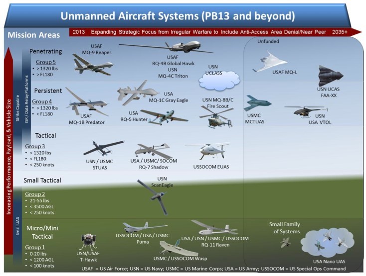
Source: Jang, C. (2017). Taking Drones to The Next Level – Cooperative Distributed Unmanned – Aerial- Vehicular Networks for Small Drones and Mini Drones. IEEE Vehicular Technology Magazine, Volume 12, Issue 3, pp. 73-82.
The Datalink – Essential Operations, Functions and Capabilities
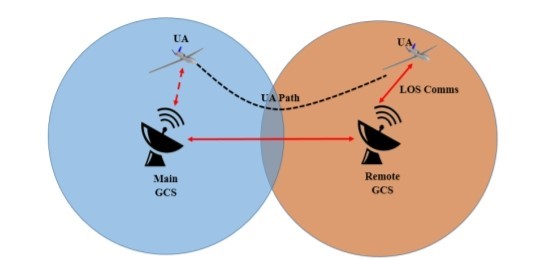
The Data-Link is essentially the neurological system for the UAS transmitting data from the eyes and ears of the operator, which is processed in their mind and then communicated through the Data-Link to the UAV either directly via line of sight, radio communication from the ground station, indirectly via satellite or via cloud-based multi-UAV networks. (See Figure 13-2 for example of a remote-controlled attack UAS, MQ-9. Think about the data-links required for this UAS.)
No matter the category of UAV, the UAS must at a minimum have the capability of the remote operator having the ability to communicate data commands to the UAV wirelessly and the UAV in turn, must be able to receive data, process commands and transmit sensor, avionic and performance data which then must be transmitted back to the ground station all of which must be safely and securely transmitted via wireless radio frequency communication.
When designing, developing and deploying UAS, there are many considerations that are vital to the successful development and robust deployment for a given application. At its core an unmanned system is designed to operate remotely in theatre by a pilot located a few feet or, as in military applications thousands of miles away.
The Data-Link is the pathway by which the UAV communicates with the ground station and operator as well as how the operator send commands to the UAV to control the its mission, evaluate changing threat vectors, navigate, respond to terrain and atmospheric condition during the mission and respond thereto as well as control intelligence gathering and in military applications, payload delivery.
The challenges presented to the UAS designer, especially when it comes to the Data-Link is how to maximize the strength of the Data-Link signal while maintaining the security of the data transmitted while protecting against possible countermeasures and threats including, but not limited to Data Jamming (“DJ), Data or Signal Deception and Anti-Radiation Munitions (“ARM”)
Figure 13-2 Remote-Controlled Attack UAS, MQ-9
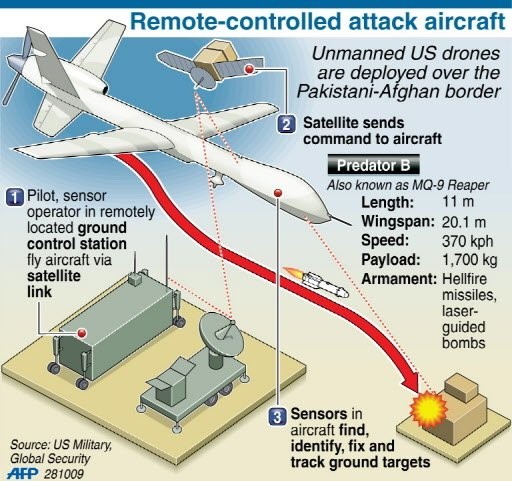
Source: Deadliest Unmanned Killing Machines in USA Arsenal. (January 01, 2011). Retrieved from https://tarwa.blogspot.com/2011/01/deadliest-unmanned-killing-machines-in.htm
All essential functions required of the UAS Data- Link communication system are:
- A ground station from which the operator can communicate via radio uplink permitting the operator to control the UAV, in terms of navigation and payload deployment.
- A downlink which is used to relay sensor, payload, and avionics data from the UAV back to the ground station and to the operator of the UAS.
- Bi-directional communication regarding distance and azimuth to the UAV to aid in precise navigation and targeting accuracy (Fahlstrom, 2012).
In addition, the Data-Link must be designed to seamlessly interface with systems onboard the UAV through the Air Data Terminal (ADT) and associated antenna arrays needed to receive radio signals from the Ground Station or satellite relayed signals in UAS that operate in beyond line of sight UAS designs.
Once received by the ADT the data must then be processed, sometimes compressed, and then instantly transmitted to the appropriate subsystems onboard the UAV such as navigation, flight surface, engine operation and targeting. Similarly, the Ground Station must also have the same abilities to receive downlink data from the UAV directly from the satellite relay. Once the downlink data is received it to must be processed, possibly compressed or converted, and then forwarded to the appropriate systems, sensors, displays or databases at the ground station.
No matter the method of transmission of the uplink or by Radio Frequency (“RF”) signals of varying frequencies are usually secured by spread spectrum techniques. (Kakar, 2017). See Figure 13-3 for a simple Data-Link.
Figure 13-3 Data Links Overlay: Ground Station, Satellite, UAS
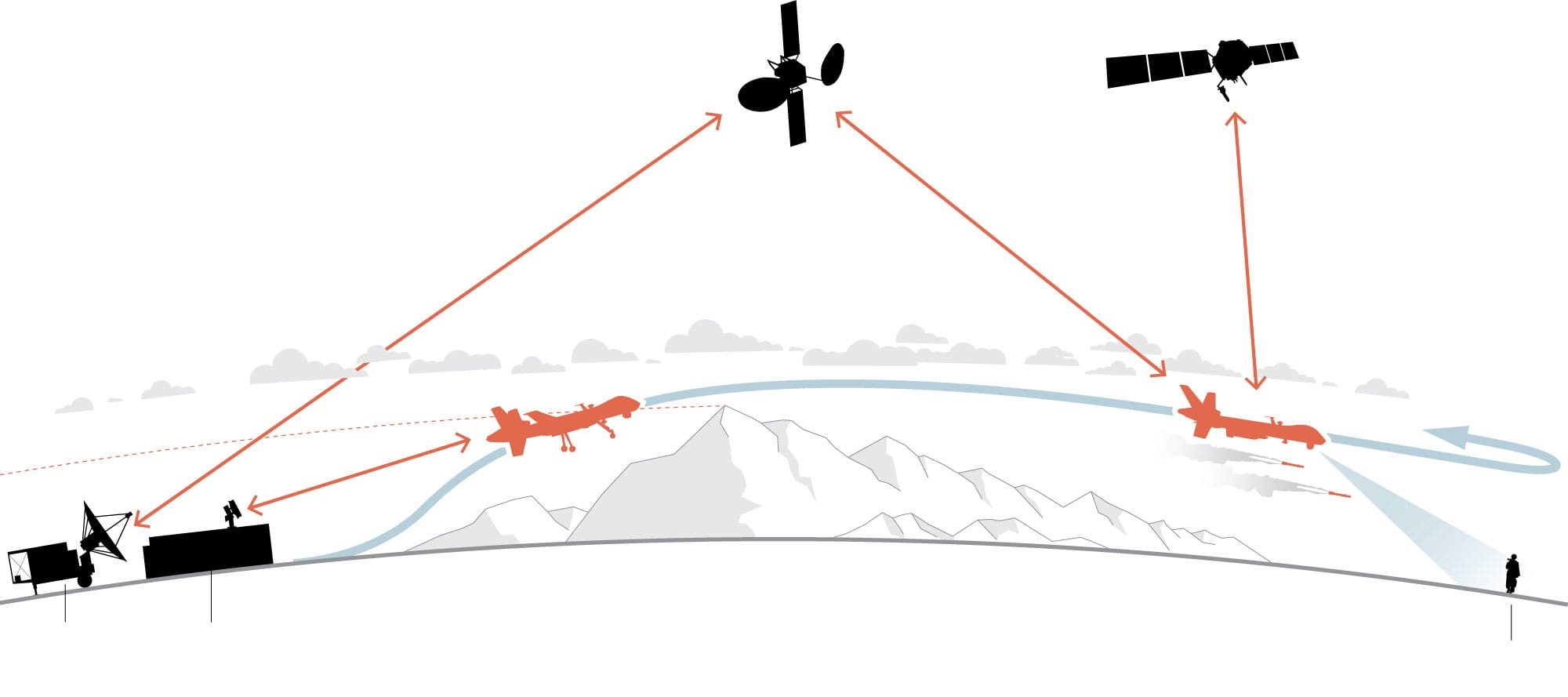
Source: Whitlock, C. (June 20, 2014). When drones fall from the sky. https://www.washingtonpost.com/sf/investigative/2014/06/20/when-drones-fall-from-the-sky/?noredirect=on&utm_term=.09b5d3e895bd
Attributes to consider in the design of the Data Link
“It is important to understand that the concept of data security in terms of the transmission, processing, storage and interpretation. It is not so much a static process but a fluid one. Given the speed with which modern technology is developed or hacked, the UAS designer should view security as a temporary” (Schneier, 2000).
“If you think technology can solve your security problems, then you don’t understand the problems and you don’t understand the technology.” (Schneier, 2000).
It is a certainty that the security of the Data Link will never be a static secure condition, it must have a robust and reactive architecture that allows it to function in geographically diverse and distant theatres globally. What may be an effective Data Link in a Nebraska field may not be in the mountains of Afghanistan.
The current consensus is that there are seven “must have” attributes of the Data Link for a UAS (Fahlstrom, 2012).
Globally available secure frequency with sufficient bandwidth and assignability. Absent this Data Link will be unable to support regular global training, testing and immediate deployment should the need arise.
- Resistance to unintentional interference. This attribute is a vital considering a myriad of other RF activities or sources may be operating simultaneously in theatre or nearby.
- Low Probability of detection and interception. The Data Link must be difficult to detect to reduce the likelihood of interception. If the Data Link signal is intercepted it becomes significantly easier for an adversary to use direction finding technology to locate and disable or destroy UAS components.
- Signal Encryption and Security. If an adversary is successful in detecting the Data Link it should not be able to locate any component of the UAS. Accordingly, Data Link encryption and decryption must be engineered into ground station, satellite and UAV.
- Anti-Deception Capability. The Data Link must securely transmit, receive and relay legitimate transmissions. Data and commands between the ground station, satellite relay and UAV must be capable of differentiating legitimate from counterfeit signals.
- ARM Resistant Capability. This attribute is especially important to the Ground Station / Operator as an Anti-Radiation Missiles (“ARM”) pose a significant threat since the Ground Station transmissions to the satellite relay and UAV are especially susceptible to this type of munition.
- Anti – Jam Capability. Similarly, to the Anti-Deception and Signal Security attributes the Anti-Jam capability requires the Data Link to maintain its functionality and efficacy, especially considering the proliferation of new and more effective Jamming technologies presently available and in development.
There is a significant amount of crossover between technologies and design elements of one attribute which may also influence another. We will discuss those “tradeoffs” in the next chapter.
Global Radio Frequency Functionality and Adaptability
What is Radio Frequency? Broadly defined in the context of UAS Data Link development it is electromagnetic radiation (EMR) being used to transfer energy and information by radio waves. Most Data Links currently use some form of wireless RF communication. Consult Figure 13-4 EMS. Certain frequencies or bands may not be available in disparate regions of the globe where conflicting RF frequencies may be in use or may not be available. Failure to account for this likelihood can result in decreased range, quality or overall efficacy of the Data Link. One of the simplest and most overlooked design attributes is limiting the use of known conflicting or unavailable frequencies, thereby enhancing robust peacetime training and actual combat deployment.
Figure 13-4 Partial EMS
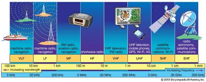
Source: VHF Communications. (2017). In Encyclopedia Britannica. Retrieved from https://www.britannica.com/technology/VHF
Without designing a UAS with global availability, the likelihood of training and testing blackout zones increases, thereby compromising rapid global deployment. The best practice is an ample consideration and allocation of frequencies available to meet known as well as unexpected contingencies. Considering that by some estimates in 2035 commercial UAS usage significantly exceed military, and governmental UAS deployments (Kakar, 2017).
Table 13-1 demonstrates the airwaves are populated with a wide array of civilian, commercial, and military Radio Frequency applications. Table 13-2 shows the RF band designations. Considering future technologies, such as global Wi-Fi, the availability of bandwidth will likely contract, while the risk of unintentional interference expands. Given the crowded low frequency airwaves, the design trend is towards VHF and even L band Data Links. This may have a positive effect upon the UAS since using higher frequency bands allows more data to be transmitted faster (Jain, 2017).
Table 13-1 Standard Definitions of Radio Spectrum Segments
Source: Spectrumeffect.com (2018)
Resistance to Unintentional Interference
Many of us who are old enough to remember the analog age will remember the heyday of AM (amplitude modulation) radio broadcasting from the 1950’s to mid – 1970’s. Although not capable of providing high quality sound, AM radio was an excellent broadcasting technology for long distances where terrain and structures may cause line of sight challenges. The downside of AM broadcasting is that is it subject to significant interference from other electromagnetic interference such as powerlines, fluorescent lights, environmental conditions and competing broadcasts. The result can be static, inconsistent signals, or even signal echo on the same frequency.
Table 13-2 shows the RF band designations.
Source: Spectrumeffect.com (2018)
The availability and allocation of overused civilian frequencies may result in new spectrums which may be more robust, powerful and secure. Incorporating new communication technologies into the UAS will help to ameliorate the challenge of Data Link interference from unintentional or environmental sources (Jain, 2017).
Examples of recently implemented tools to mitigate interference include using cellular technology and power control framework (Yajnanarayana, 2018). Encryption of RF signals may provide additional interference protection as will new cable, connector and power supply shielding (Cannon Corporation, 2017). Lastly novel approaches are currently being developed including a self-interference cancellation solution where the UAS Data Link will self-detect and correct interference by situationally moving to other RF bands and frequencies (Chen, 2014).
Low Probability of Intercept (“LPI”)
LPI is a vital attribute for the Datalink if for no other reason than it is the most likely source of human casualties. In most instances it is desirable to have the ground station in proximity to the operator or pilot of the UAV. Distance matters in UAS design since the greater the distance data must travel, the greater the latency.
The threat of interception of the RF emissions from the ground station an essential attribute of the uplink design. Less likely, though still a design concern is in certain instances the downlink can be targeted for interception. One scenario where interception risk to the downlink increases is when a UAV is hovering for extended periods of time. Not only will this put the UAV at risk of attack but also the risk that the downlink communications may be intercepted increases and consequentially the target of the surveillance may be alerted to its presence, causing them to camouflage or cease activities.
Electronic Support Measurement (ESM) systems allow adversaries to locate the source of RF emissions in an area. This technology is especially effective in locating the ground station since it is usually stationary for extended periods of time. The longer a source emits radiation, the greater the chance of interception. Since it is not feasible to constantly move the ground station increasing LPI can seem to be daunting task. Another relatively simple, yet effective methods to minimize the risk of intercept is by increasing armaments and location of the ground station. Shielding vital components and pilots from an attack can help ensure UAS and personnel survivability in the case of a successful interception attack. Finally, designers should not be comfortable in the assumption that LPI is inherent higher in a moving UAV. Innovative technologies capable of detecting and intercepting signal emanations from moving objects are becoming more effective and readily available.
Effective enhancement of LPI can be accomplished by some of the following tactics and technologies:
- Ground Station Handover Method. (GSHM)
- Direct-sequence spread spectrum (DSSS)
- Frequency-hopping spread spectrum (FHSS).
- Dynamic power management. (DPM)
- Directional transmission. (DT)
- Low duty cycle methods (LDCM) (Okcu, 2016). See Figure 13-5 Overlay.
Figure 13-5 LDCM Method Overlay
Source: Okcu, H. (2016). Operational Requirements of Unmanned Aircraft Systems. Journal of Advances in Computer Networks, Vol. 4, No. 1, 28-30.
Signal Encryption and Security
Best practice in all areas of information security is constantly enhancing inaccessibility of the data and components of a network or system. This seemingly simple concept is no less relevant when designing a UAS Data Link. The wireless RF Data Link is an enticing target one which if successfully attacked can disable or damage multiple systems connected to the Data Link. Here is a list of some recent Data Link hacks upon civilian, commercial and military UAS.
- Maldrone, where malware is injected into critical areas of the UAS operation system through security flaws in the Datalink.
- GPS Spoofing is a hack which essentially can alter or delay UAV commands via GPS and accordingly can cause collisions, faulty guidance and theoretically virtual UAV hijacking whereby a civilian UAV can be turned into an attack vector against military UAV’s even though military GPS systems are well protected. This was used by the Iranian military to capture a United States military drone in 2011.
- Zigbee and Killerbee which are essentially sniffing and penetration tools which when successful can cause a major threat to UAS by Denial of Service attacks (Rodday, 2015).
Data encryption is a vital tool to create a secure Data Link. Just as in wired computer networks, the wireless UAS employs CPU’s and operating systems to perform functions involving massive amounts of data which must be immediately processed and transmitted internally and externally.
An exciting new protocol is the Commercial Solutions for Classified Program (“CSfC”), developed United States National Security Agency – Central Security Service. This is a layered approach to data security for UAS where two or more commercially available encryption and cybersecurity protocols provide enhanced Data Links security. The layered approach is beneficial since it reduces development time and expense while leveraging crossover of cybersecurity threat similarities across civilian, commercial or military applications (Keller, 2016). See Figure 13-6 Harris KGV-72 encryption device for secure messages.
Whatever the protocol or technology Data Link security must not only address the threats known today but also capable of adjusting to new threats as they are discovered. Constant evaluation, testing, and even “white hat” hacking is one of the best insurance policies against attacks. It is far better to discover a vulnerability or security flaw while the UAS is being tested and used for training as opposed to during an actual operation.
Figure 13-6 Harris KGV-72 encryption device for secure messages
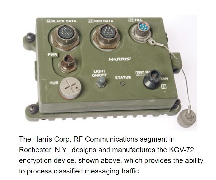
Source: Harris Corporation. (2009). Kgv-72 Type-1 Programmable Encryption Device. http://jproc.ca/crypto/kgv72.pdf
There is no security without physical security. It has been estimated that up to 95% of all security incidents in 2014 were the result of human error (Howarth, 2014). The best Data Link security requires constant technological examination as well as robust physical security. Physical security and access controls must be implemented and enforced for all who operate, meet, provide third party support or services to the UAS design and operations team.
Resistance to Deception
A closely related, yet separate attribute of Data Link design is avoidance of deception by an adversary. Spoofing an apparently authentic command or GPS direction data can cause a UAV to become uncontrollable or even crash. Deception resistance is currently a focal concern with respect to the data uplink between the ground station and UAV. Just one deceptive command can cause a UAV to crash, be captured, hijacked or even attack a friendly target.
Not only can deception cause these types of undesirable consequences, a successful effort can also jeopardize a wide array of secrets and information. Although it remains unclear whether jamming or deception was used, it is believed that Iran has re-engineered a US built RQ-170 Sentinel Drone which was captured by some form of deception or jamming in December, 2011(Opall-Rome, 2018). See Figure 13-7 Enemy Captured RQ-170.
Currently there are multiple methods to achieve an acceptable level of resistance to this form of attack. Many methods that help protect the Data Link from other security threats will also provide protection against deception attacks. Those include, Spread Spectrum Data Link transmissions using secure authentication codes. These codes can be a software embed in the ground station transmission to the satellite relay or UAV. Both the UAV and ground station will have encoding and decoding software to authenticate commands without direct modification to the uplink. (Fahlstrom, 2012) If a satellite relay is implemented in the UAS it can also have authentication software thereby establishing end-to-end data security. Anecdotally, AJ and LPI can also be enhanced by encoding Data Link transmissions.
Figure 13-7 Enemy Captured RQ-170
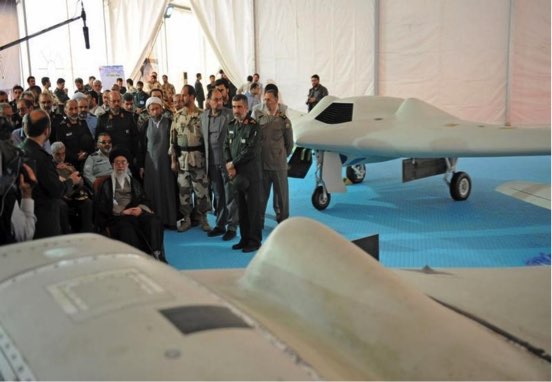
Source: Opall-Rome, B. (February 12, 2018). Israel Air Force says seized Iranian drone is a knockoff of US Sentinel: https://www.defensenews.com/global/mideast-africa/2018/02/12/israel-air-force-says-seized-iranian-drone-is-a-knockoff-of-us-sentinel/
One particularly promising GPS spoofing detection systems was hypothesized by a team at Cornell University in Ithaca, New York. This spoofing detection system essentially “spoofs’ the Spoofer. Below is a figure of the proposed system architecture for this yet potential anti-deception system.
As depicted above, three Global Navigation Satellite System (GNSS) satellites whose signals would be tracked in the non-spoofed case: satellites j-1, j, and j+1. It also shows the potential location of a Spoofer that could send false versions of the signals from these same satellites. The Spoofer has a single transmission antenna. Satellites j-1, j, and j+1 are visible to the receiver antenna, but the Spoofer could “hijack” the receiver’s tracking loops for these signals so that only the false spoofed versions of these signals would be tracked by the receiver” (Psiaki, 2013). See Figure 13-8 Spoofing the Spoofer.
Figure 13-8 Spoofing the Spoofer
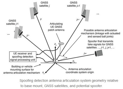
Source: Kakar, J. M. (2017). Waveform and Spectrum Management for Unmanned Ariel Systems Beyond 2025. Ithaca, New York: arXIv.org, Cornell University.
This and other recent technologies which can aid in securing the UAS Data Links of civilian, commercial and military UAS applications is an important reminder of the fluidity of the discipline. As the ancient Chinese Philosopher Sun Tzu wrote of 2500 years ago in “The Art of War”,
“The whole secret lies in confusing the enemy, so that he cannot fathom our real intent.” Words matter when it comes to avoiding detection, but perhaps more importantly understand that the unexpected should always be expected when (Giles, 2013)
When it comes the securing a UAS Datalink designers would be wise to live by these it comes to technological warfare and cyber -attacks against military technology.
Anti-ARM
Anti-Radar Missile (ARM’s) sense and target sources of RF signals radiation to provide an attack vector to destroy the emission source. Since a UAS Data Link, especially the uplink, emits RF radiation from the ground station transmission antenna, it is susceptible to being attacked by ARM weaponry.
ARM threat only exists when RF radiation is emitted. Limiting RF transmissions to instances when commands are being sent is a simple yet effective Anti-ARM defense. In addition, various decoy technologies exist to reduce the ARM threat as well as placing the transmission antenna farther away from the Ground Station to minimize ARM damage. Finally, various signal spectrum spreading techniques, not to mention physical armor for the Ground Station itself will all increase the Anti- ARM characteristics of the UAS Datalink. (Fahlstrom, 2012)
Other proposed Anti – ARM capabilities involve hardening the Ground Station and particularly the antenna array. On such proposal is to quickly identify and then react to the signature of an incoming ARM and rapidly recoil a more heavily armored antenna before an ARM which successfully penetrates other Anti-Arm defenses. This proposal is an important example of physical security, even the age of technology can still be an excellent defense. When one considers the millions of dollars involved in design, development and deployment of UAS, it makes sense to harden its battlefield armor. It most certainly better to be able to have a UAS survive an ARM attack and be re-deployed to re-engage the enemy. (Czeszejko, 2013) See Figure 13-9 ARM Processes.
Anti-Jam (AJ) Capabilities
If one considers ARM threats an attack vector based upon the source of the Data Link communications, then jamming can be considered UAS countermeasure designed to address signals containing commands that are transmitted by the ground station. Jamming is a countermeasure used to inhibit the ability of a UAV to successfully communicate with its operator by directing powerful electromagnetic radiation (“noise”) at the Data Link in order to “drown out” communications and data transfer. Similarly, global navigation satellite system jamming can impede the pilot’s ability to fly the UAV increasing risk of a catastrophic failure or crash (Droneshield , 2017).
Jamming the GNSS data flow between the UAV and pilot takes away the eyes and ears of the UAS. Without the ability to guide itself or be flown by a pilot using GNSS data, exponentially increase the risk of crash, mission failure, loss of life and investment.
Figure 13-9 ARM Processes
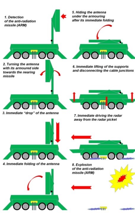
Source: Czeszejko, S. (2013). Anti – Radiation Missiles vs. Radars. In International Journal of Electronics and Telecommunications, 59(3), 285-291.
Jamming is an attack similar in nature to a brute force attack upon a network. Instead of using technology to randomly generate massive amounts of passwords or passphrases, jamming is intended to overwhelm the Data Link with RF noise or static (remember the AM radio example). Recent history demonstrates the efficacy of successful jamming. During the Russian incursion into Crimea and Ukraine separatist conflict in 2014 Russian jamming effectively kept the eyes and ears of the world from observing their activities (Hudson, 2016).
Increasing the AJ of a UAS can be achieves in multiple ways. First necessary to determine the amount of jamming radiation (noise) the Data Link can withstand before its ability to function falls below minimal acceptable levels. This is referred to as the AJ margin and is usually measured in decibels (dB) (Fahlstrom, 2012).
One technique for increasing the AJ margin U is implementing Spread Spectrum Communication.
“Spread spectrum is a means of transmission in which the signal occupies a bandwidth in excess of the minimum necessary to send the information; the band spread is accomplished by means of a code which is independent of the data, and a synchronized reception with the code at the receiver is used for dispreading and subsequent data recovery.” (Pickholtz, 1982)
Other techniques to increase AJ Margin include:
- Adaptive Filtering (AF)
- Time – Frequency Domain Filtering (FDF)
- Adaptive Antennas (AA) (Iqbal, 1991).
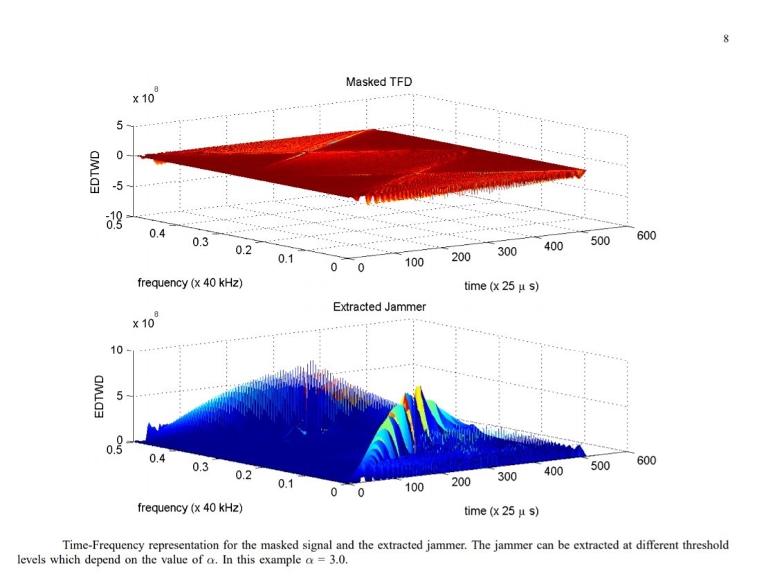
One technique, Bilinear Signal Representations (“BSR”), also seems to hold great promise. Essentially BSR identifies jamming signals, separates them and then re-synthesizes legitimate Datalink signals (Kandangath, 2003) (Collins, 2013). See Figure 13-10 and Figure 13-11 for BSR Representations.
It is also important to remember that jamming is solely a concern in relation to the uplink, in fact preprogrammed flight instruction can still allow a successful mission when jamming successfully drowns out signal from the Ground Station to the UAV. However, if the downlink is jammed the ability for the operator to receive real time data can be diminished or disrupted thereby eliminating the flexibility for the controller to make on-the-fly adjustments or changes to the mission (Fahlstrom, 2012)
Figure 13-10 BSR Representation
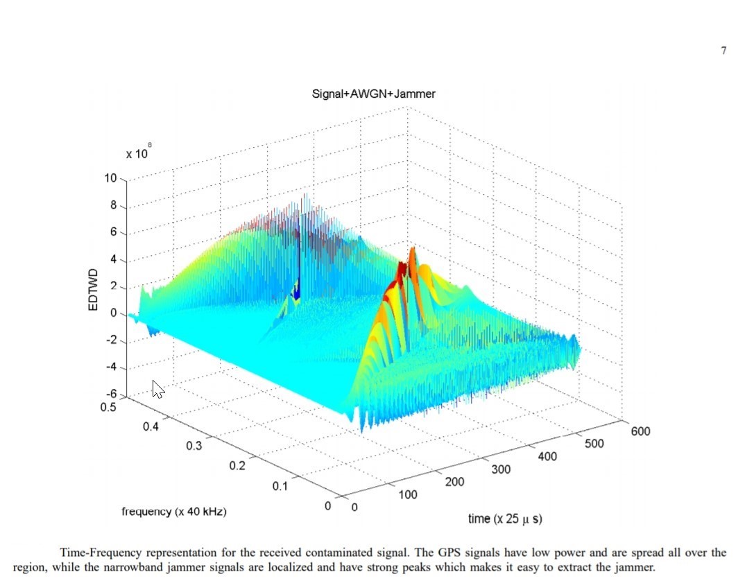
Source: Kandangath, A. (2003). Jamming Mitigation Techniques for Spread Spectrum Communication Systems. Tempe, AZ: University of Arizona, Tech. Rep., 2003.
Figure 13-11 BSR Representation (alt)
Source: Kandangath, A. (2003). Jamming Mitigation Techniques for Spread Spectrum Communication Systems. Tempe, AZ: University of Arizona, Tech. Rep., 2003
Additional Considerations
Digital vs Analog
Analog signals are a method of data transmission data which vary with time, they are inherently low-latency because they travel at the speed of light (Reid, 2017). The evolution of wireless Data Links favors digital modulation. This makes sense since most data processing activity throughout the UAS requires digital data or analog data converted to digital. Higher interference margin, ease of interfacing between components and systems support conclusion that to the extent practical, Data Link communication should favor digital data transmission(United States Marine Corps, 2015) (Fahlstrom, 2012).
One caveat to the favored use of digital data transmission. Digital transmission handles far more data much faster than analog. If successfully intercepted and decrypted an adversary can extract massive amounts of data, intelligence, intellectual property and even top-secret information. An example of such a threat occurred in 2017 when the United States Army banned the use of DJI drones, a Chinese manufacturer. (Mortimer, 2017) See Figure 13-12 US Army Warning Letter.
System Interface Considerations
Maximizing the efficacy of the Data Link requires that transmission be secure and resilient while capable of swiftly delivering accurate data. The Data Link payload must be capable of interfacing and supporting four types of critical UAS functions:
- Aircraft Control, everything but payloads and weapons
- Payload, product and control
- Weapons, kinetic and electronic
- Situational Awareness (United States Department of Defense, 2005).
Figure 13-12 US Army Warning Letter
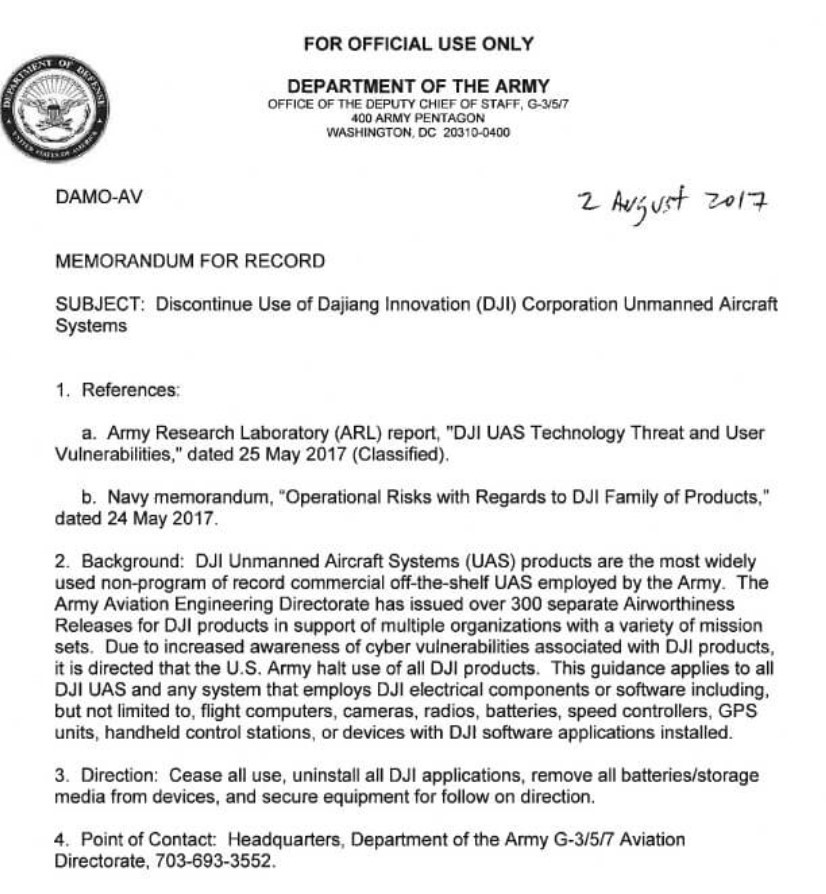
Source: Scott, A. (2017, August 4). U.S. Army halts use of Chinese-made drones over cyber concerns. Reuters. AND Mortimer, S. (2017, August 4). US Army calls for units to discontinue use of DJI equipment. sUAS News.
Data Link delivery of secure, high-speed data allows electronic systems to interface seamlessly with mechanical system must also be capable of concurrent self-monitoring and agile reaction to attacks. This attribute allows accurate communication between the ADT, ground station and entire UAS network (Fahlstrom, 2012).
Lastly a cautionary note. Meeting data requirements may negatively impact AJ margin and deception resistance which can be far more difficult and expensive to remedy after the original design process (Saeedipour, 2005). Simply because UAS design deals largely with the cyber realm, should not be taken as license to ignore brick and mortar reality. Specifically, Newton’s Third Law, “for every action, there is an equal and opposite reaction” takes on new significance when considering which Data Link attribute should be emphasized and which may be subject to trade-off (Sunil, 2008).
Data-Rate
Data rate is a vital since the pilot sends commands through the uplink to the UAV the result of the command execution are confirmed by onboard sensors, video or other indicators to confirm execution. If the data rate of the downlink is not sufficiently robust latency comes into play. In NLOS configurations, the execution data is sent by the ADT to a satellite and then relayed via downlink to reach the operators eyes. Inadequate data rate can cause many unwanted consequences from duplicate commands, expired intelligence, total failure of the mission or loss of the UAV.
The data lifecycle of a UAS underscores the imperative of data rates capable of handling vast amounts of data during a UAV mission. As the figure below depicts just a UAS functions demonstrate the importance of rapid data transmission, as well as high speed onboard and ground-based data processing. See Figure 13-12 Data Lifecycle of UAS.
Figure 13-13 Data Lifecycle of UAS
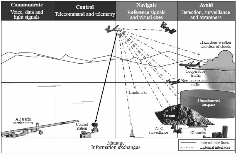
Source: International Telecommunication Union. (2009). Characteristics of unmanned aircraft systems and spectrum requirements to support their safe operation in non-segregated airspace. Geneva, Switzerland: International Telecommunication Union.
It is important to note the figure above only depicts the en route portion of a mission. In actuality the bi-directional data flow commences with pre-flight communication and instruction, continues through departure, en route, arrival and post-flight. Coupled with payload, handover, contingency, time stamping and emergency contingency planning to the data flow to these phases it becomes readily apparent that data rate is a seminal issue in the UAS design process. (International Telecommunication Union, 2009)
Finally the exponential growth of UAV’s in service globally, consideration of the finite supply of bandwidth and how to best account for the available bandwidth will most certainly involve attribute trade-offs. Difficult choices will need to be made regarding bandwidth availability as it relates to specific missions, geography and available wireless technology. Accordingly, instead of designing regional as opposed to globally adaptable UAS, best practice as well sound budgetary policy dictates that interchangeability and interoperability be prioritized.
Closed Loop Control
Certain aspects of UAS design can benefit from employ using loop control between a UAV and the same or another location. While it is possible to pre-program the UAV recovery process, human intervention in this phase of the mission will ensure an agility in adapting to changing physical, environmental or threat conditions in the landing zone.
Given the highly variable conditions in the landing and retrieval zone, it is often the case that a separate closed loop Data Link, between the UAV and pilot can enhance safely and effectively retrieving the UAV. Closed loop Data Links require a additional reception and processing capability onboard both the UAV and ground station.
The threats to closed loop control systems are no different than in the main Data Link. Latency, restricted bandwidth, AJ, deception, and line of sight are important considerations. Although discussed latency later in the chapter when it comes to closed loop control, especially video transmission of approach and recovery, the margin of error becomes smaller with declining altitude, limited runway length, environmental and physical conditions in the landing zone. (Fahlstrom, 2012)
Imagine operating a video game or flight simulator on a desktop or gaming console and the visual representation presented on the screen was actually delayed by 2 seconds (ie. Aircraft appears to be 1 mile away from target when it is actually .6 miles away from the target). A command to reduce power and altitude on a one mile glidepath subject to a 2 second delay becomes far more challenging. Suffice it to say the game would not last very long, nor would it be very successful. See Figure 13-14 Flight Simulation Game.
Figure 13-14 Flight Simulation Game

Source: Neuroscape. (Summer, 2018). Technology: Bridging the gap between neuroscience and technology. https://neuroscape.ucsf.edu/technology/
Interchangability, Interoperability and Standarization
At first glance it appears Interchangeability and Interoperability ( I & I) are the same thing. In reality they are distinct concepts which require separate analysis and consideration of the UAS design process (Yu, 2016).
Some, such as Fahlstrom consider I & I separate and distinct attributes, writing “interoperability would mean that an ADT from one data link could communicate with a Ground Data Terminal (“GDT”) of another and vice versa.” (Fahlstrom, 2012) p. 201-202. While others such as Yu, seem to blend I & I into one concept citing the 1999 Joint Chiefs of Staff definition is, “The ability of systems, units or forces to provide services from other systems, units or forces and use the services so exchanged to enable them to operate effectively together.” (United States Department of Defense, Joint Chiefs of Staff, 2016) (Yu, 2016).
Finally, standardization must be considered from the moment of initial design of the UAS. If the system is to have a sufficient service life thereby justifying the expense of its development, standardization with the myriad of other systems is essential.
Standardization is a set of “requirements, specifications, guidelines, or characteristics that can be used consistently to ensure that materials, products, processes and services are fit for their purpose.” (Standardization, 2017) In 1998 NATO began to consider methods by which technology can be built with uniform standards and interoperability. As unmanned warfare accelerated towards the end of the last century, NATO began to develop protocols to enhance and ensure standardization between member nations and their technology.
STANAG 4856 – Standard Interfaces of UAV Control System (UCS) for NATO UAV interoperability was created in order to maximize communication between, “different UAV’s and their payloads, as well as different Command, Control, Communication, Computers and Intelligence systems. The integration of components from different sources as well as the interoperability of legacy systems.” (Marques, 2017) Designers must not just consider the reality that interoperability between allied UAV’s, they must also consider the challenge of maximizing interoperability with other assets. Figure 13-15 JTIDS view below demonstrates just some of the myriad of systems which must to be able to operate and communicate, in real time, as seamlessly as possible.
Figure 13-15 JTIDS View
Source: GlobalSecurity.org. (Summer, 2018).Joint Tactical Information Distribution System (JTIDS). https://www.globalsecurity.org/military/systems/ground/jtids.htm
The challenge to designing Interoperability and Standardization (I&S) in UAS design is multifold with the battlefield attributes of central command, communication and coordination taking center stage. The ability of allies to communicate is vital for cohesive, coordinated and effective operations.
Recognizing the importance of I&S, the Department of Defense is developing a Joint Architecture for Unmanned Systems, (“JAUS”), National Information Exchange Model (“NIEM”) and most recently Future Airborne Capability Environment (FACE). The objective of FACE is to develop a “Technical Standard for a software capability designed to promote portability, and create software product lines across the military aviation community.” (Blais, 2016).
Datalink Latency
The Current Environment
Latency is defined as the interval between the time when data is processed and a signal is transmitted and when the signal is received and then processed in order to be displayed and interpreted by the operator. To help understand latency ask yourself why do we see lightning before we hear thunder? See Figure 13-16 Lightning Strike and Latency.
Light is an electromagnetic wave which needs no through which to travel. It moves at 300,000,000 meters per second, so a lighting strike in your general vicinity is seen by the naked eye almost immediately. On the other hand thunder is sound, a mechanical wave which needs to travel through a medium, in this case air molecules. Sound travel through air at a speed of 340 meters per second which is approximately one million times slower than the speed of light. Hence lightning will be seen before thunder is heard due the latency of the transmission of sound as opposed to light (Park, 1997).
Figure 13-16 Lightning Strike and Latency
Source: NASA, Glenn Research Center. (Summer, 2018). Speed of Sound. https://www.grc.nasa.gov/www/k-12/airplane/sound.html
Returning to the UAS datalink, line of sight visual transmission and reception is ordinarily nearly instantaneous because of the speed of light. Unfortunately line of sight, environment and distance significantly limit UAV operational radius. Even LOS operation of a UAV can be hindered by weather, vegetation, time of day and topography. Air and ground traffic density become more problematic with greater latency (International Telecommunication Union, 2009).
According to some estimates domestic airspace must be able to accommodate up to 10 million combined air vehicles a day by 2035. When you consider that in 2015 that in US airspace was traversed 50,000 times per day such an exponential increase will be problematic (Atkinson, 2015).
Flight Control Technology
Presently there are 3 classes LOS UAV operation:
- Low Endurance
- Medium Endurance; and
- High Endurance (Valavanis, 2013).
Low Endurance:
Operate almost exclusively in line of sight with a minimum of automated onboard flight control technology. Usually LOS UAS employ C Band frequency with low frequency of between 3.7-4.2 GHz for the downlink and 5.9-6.4 for the uplink. One of the main reasons for C Band datalinks in Low Endurance UAS is that low frequency signals are less susceptible to weather related degradation.
Medium Endurance
Operate in primarily in LOS applications however some do have Beyond Line of Sight (“BLOS”) capability. To the extent they are operating in LOS missions lower frequency C Band is used, if the Medium Endurance UAS is deployed BLOS then they usually will usually be operating on Ultra High Frequency (“UHF”) (300 MHz) to Ku Band (15 GHz). The downlink is between 11.7 – 12.7 GHz and the uplink between 14-14.5 GHz.
High Endurance
High Endurance UAS deployed BLOS operate on Ultra High Frequency (“UHF”) (300 MHz) to Ku Band (15 GHz). Downlink frequency is between 11.7 – 12.7 GHz and uplink between 14-14.5 GHz. High Endurance UAS may also employ Common Data Link (“CDL”) technology on either I-band satellite communication (“SATCOM”) or KU band between 14.5 and 15.38 GHz. To minimize SATCOM latency autopilot is often favored in LOS RF operations (Valavanis, 2013).
The trade-off between security and latency is a difficult balance to achieve. US Air Force Major General James Poss. (Ret.) put it best.
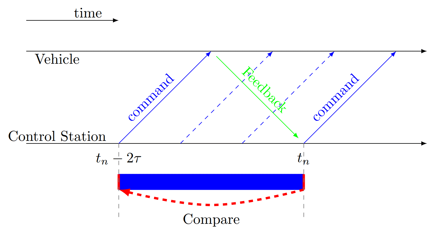
“Even the Air Force struggles with this problem because the more secure they make their links, the more control latency and potential for link loss they introduce. At least with today’s technology. Air Force Predator pilots routinely deal with a five to eight second delay on their controls when flying BLOS due to encryption overhead and the time it takes to relay commands via satellites” (Poss, 2017). Consult Figure 13-17 Security – Latency Trade-off.
While there are options to minimize latency while balancing the attributes needed for a robust and effective UAS Data Link, latency is a constant in any transmission travelling any distance. The greater the distance, the more time to travel. The greater the data payload the more time to transmit.
Innovative technologies designed to address latency in UAS Data Links are presently being studied. One that may hold much promise is the introduction and continued development Artificial Intelligence in UAS design. To be sure the less data that needs to be sent to the UAV on the uplink or back to the ground station on the downlink, the less latency in executing commands and near-real time UAV control. (Bennis, 2018) AI holds much promise but must also be considered a risk. Just as a UAV pilot could become incapacitated or go rogue, the same risks exist with AI implementation in UAS.
Figure 13-17 Security – Latency Trade-off
Source: UAV Research Lab at the University of Sydney. (2018). Adapting UAV Control for Latency. UAV – Lab.
Discussion Questions
- Since so many attributes of a UAS have distinct levels of importance depending on environment, mission and payload, how can the designer create a system that is agile, and globally deployable, thereby increasing service life and efficacy while still being sensitive to the cost of development?
- How would you rate each of the attributes discussed in this chapter and are there other attributes you think need consideration?
- If UAS countermeasures continue to evolve, what is the best method of ensuring that current attributes and functions remain effective?
- Bearing question 3 in mind, at what point does cost of development exceed the value service life of a UAS? How would such an analysis be made and what factors would you consider relevant?
References
Atkinson, N. (2015, September 7). Designing a way to keep increasingly crowded airspace safe. phys.org.
Bennis, M. D. (2018). Ultra- Reliable and Low-Latency Wireless Communication: Tail, Risk, Scale. arXil.org.
Blais, C. L. (2016). Unmanned systems interoperability standards. Monterey CA: The Naval Postgraduate School.
Cannon Corporation. (2017). Shielding against electromagnetic and RF interference for safety and mission success. Military and Aerospace Electronics, 1.
Chen, J. (2014). MIMO Enhancements for Air-to-Ground Wireless Communications. Los Angeles: UCLA Electronic Theses and Dissertations.
Collins, T. F. (2013). Implementation and Analysis of Spectral Subtraction and Signal. Worcester, MA: Worcester Polytechnic Institute.
Congressional ResearchService. (2018). Artificial Intelligence and National Security. Washington, DC: Congressional Research Service.
Czeszejko, S. (2013). Anti – Radiation Missiles vs. Radars. International Journal of Electronics and Telecommunications, 285-291.
Droneshield . (2017). Drone Defence: Jammers 101. 1.
Fahlstrom, P. G. (2012). Data – Link Functions and Attributes. In P. G. Fahlstrom, Introduction to UAV Systems, Fourth Edition (p. 193). John Wiley & Sons, Ltd.
Giles. (2013). Sun Tzu On The Art of War. Abingdon, Oxon: Routledge.
Hartman, K. &. (2013). The Vulnerability of UAV’s to Cyber Attacks – An Approach to the Risk Assessment. 5th International Conference on Cyber Conflict. Tallin: NATO CCD COE Publications.
Howarth, F. (2014). The Role of Human Error in Successful Security Attacks. Armonk, NY: IBM – Security Intelligence.
Hudson, J. (2016, October 28). International Monitor Quietly Drops Drone Surveillance of Ukraine War. Foreign Policy.
International Telecommunication Union. (2009). Characteristics of unmanned aircraft systems and spectrum requirements to support their safe operation in non-segregated airspace. Geneva, Switzerland: International Telecommunicaton Union.
Iqbal, R. B. (1991). Performance Analysis of Interference Rejection Techniques in Spread Spectrum Communication. TENCON 91′ IEEE Region 10 International Conference on EC3-Energy, Computer, Communication and Control Systems, Vol. 3. IEEE.
Jain, R. T. (2017). Wireless Datalink for Unmanned Aircraft Systems: Requirements, Challenges and Design Ideas. American Institute of Aeronautics and Astronautics, 2.
Jang, C. e. (2017). Taking Drones To The Next Level – Cooperative Distributed Unmanned – Aerial- Vehicular Networks for Small Drones and Mini Drones. IEEE Vehicular Technology Magazine, Volume 12, Issue 3, pp. 73-82.
Kakar, J. M. (2017). Wavefrom and Spectrum Management for Unmanned Ariel Systems Beyond 2025. Ithaca, New York: arXIv.org, Cornell University.
Kandangath, A. (2003). Jamming Mitigation Techniques for Spread Spectrum Communication Systems. Tempe, AZ: University of Arizona, Tech. Rep., 2003.
Keller, J. (2016, August 1). Cybersecurity and encryption for the masses. Military and Aerospace Electronics.
Marques, M. M. (2017). STANAG 4586 – Standard Interfaces of UAV Control System (UCS) for NATO UAV Interoperability. Brussels, Belgium: North Atlantic Treaty Organization .
Mortimer, G. (2017, August 4). US Army calls for units to discontinue use of DJI equipment. sUAS News.
Nuriev, N. G. (2017). Physical modeling of electromagnetic interferences in the unmanned aerial vehicle in the case of high-voltage transmission line impact. Russian Aeronautics, 292-293.
Okcu, H. (2016). Operational Requirements of Unmanned Aircraft Systems. Journal of Advances in Computer Networks, Vol. 4, No. 1, 28-30.
Opall-Rome, B. (2018, February 12). Israel Air Force says seized Iranian drone is a knockoff of US Sentinel. Defense News.
Park, C. C. (1997). The Environment: Principles and Applications. London, UK: Routledge.
Pickholtz, R. L. (1982, May). Theory of spread spectrum communications – a tutorial. IEEE Transactions on Communications, Vol. 30 No. 5, pp. 855-884.
Poss, M. G. (2017, February 22). It’s the Data Link Stupid. inside Unmanned Systems.
Psiaki, M. L. (2013, June 1). Innovation: GNSS Spoofing Detection. GPS World.
Reid, J. (2017, November 30). The Difference Between Analog and HD (Digital) Transmission. Rotor Drone Magazine.
Rodday, n. (2015). Exploring Security Vulnerabilities of Unmanned Aerial Vehicles. Amsterdam: University of Twente.
Saeedipour, H. R. (2005). Data Link Functions and Attributes of an Unmanned Aerial Vehicle IUAV) System Using Both Ground Station And Small Satellite. 5th IAA Symposium on Samm Satellites for Earth Observation. Berlin, Germany: International Association of Astronautics.
Schneier, B. (2000). Secrets and Lies, Digital Security in a Networked World. Hoboken, NJ: John Wiley and Sos, Ltd.
Scott, A. (2017, August 4). U.S. Army halts use of Chinese-made drones over cyber concerns. Reuters.
Standardization, I. O. (2017). “Standard”. http://www.iso.org/iso/home/standards.htm.
Sunil, K. S. (2008). Newton’s third law of motion. Houston, TX: Rice University.
UAV Research Lab at the University of Sydney. (2018). Adapting UAV Control for Latency. UAV – Lab.
United States Department of Defense. (2005). Unmanned Aircraft Systems Roadmap 2005-2030. Washington, DC: Office of The Secretary of Defense.
United States Department of Defense, Joint Chiefs of Staff. (2016). Department of Defense Dictionary of Military and Associated Terms – Joint Publication 1-02. Washington, DC: United States Department of Defense.
United States Marine Corps. (2015). Unmanned Aircraft Systems Operations. Washington, DC: Department Of The Navy.
Valavanis, K. P. (2013). Unmanned Aircraft Systems: the Current State-of-the-Art. New York: Springer.
Yajnanarayana, V. W.-P. (2018). Interference Mitigation Methods for Unmanned Aerial Vehicles Served by Cellular Networks. https://arxiv.org/pdf/1802.00223.pdf
Yu, A. M. (2016). Unmanned Aircraft Systems. Hoboken, New Jersey: John Wiley and Sons.
