Chapter 7: UAS SAA Methodologies, Conflict Detection
Student Learning Objectives
In Chapter 3: Understanding Hostile Use and Cyber-Vulnerabilities of UAS: Components, Autonomy Vs. Automation, Sensors, SAA, SCADA and Cyber Attack Taxonomy, the student was exposed to the Counter UAS problem and UAS Vulnerabilities. The heart of any UAS system are its Sense and Avoid Systems (SAA). It is the key to understanding threats and vulnerabilities of the UAS. Understanding SAA methodologies, conflict detection and conflict resolution principles is best practice. In Chapter 7, the student was introduced to SAA sensing practice and a logic case for conflict detection and resolution using the sensing data. Along with Chapter 8: Designing UAS systems for Stealth and Chapter 9 Smart Skies Project, the student should be versed on the dynamics and importance of SAA.
Sense and Avoid (SAA) Function
“The purpose/function of SAA is to remove and replace a human pilot, to detect and resolve certain flight hazard s. Hazards consist of other traffic or ground objects; anything that presents a risk of collision. UAS is unmanned. SAA systems are not necessarily designed to preserve the aircraft. SAA is certainly designed to prevent collisions, ground personnel, and collateral damage to property. SAA must operate for emergency and diversionary events as well as normal operations.” (Zeitlin, 2012)
“Human pilots on manned aircraft are required to See and Avoid (also identified as SAA) hazards. They do this with regular visual scans across their Forward Field of View (FFoV) to detect another A/C.” Pilot “scanning may be focused toward areas where operations are on-going or informed by controller over radio traffic or by electronic display on an Automated Identification System (AIS) for collision avoidance.” (Zeitlin, 2012) Traffic spotted means the pilot must judge “its trajectory relative to their own A/C and determine the risk of collision and whether an A/C maneuver is required. (Zeitlin, 2012) Humans are at disadvantage for the See and Avoid process especially in poor weather, when backgrounds are confusing, when visibility is reduced, or pilot workload is excessive.
UAS come in all sizes and capabilities. Those that can be outfitted with robust SaA equipment, can overcome the human limitations. “Some UAS are too small to carry weighty SAA equipment. These A/C can operate within direct radio communication of the pilot and to maintain a Visual Line of Sight (VLoS) between pilot and A/C.” (Zeitlin, 2012) Small UAS may have additional restrictions that preclude operating over densely populated areas, near airports, or total weight capacities.
System Configurations and Subsystems
Chapter 3 addressed onboard / off-board SAA configurations, sensors and surveillance volume, sensor capabilities, typical sensors, coordinate systems, ground-based sensing, sensor parameters, self-separation schemes, SAA services and sub-functions with timeline, and SCADA. Additional material to these topics follows.
Sensor Categories
UAS robotic aircraft flights are primarily to collect data. The data collected can be broken down into two broad categories: in situ[1] and remote sensing. These two methods are used to collect vast amounts of intelligence, including an enemy’s dispositions of forces and probable intentions. (Marshall, 2016)
In situ Sensing
In situ sensing in a UAS means the aircraft is transported to the location where measurements are to be made. There are two methods: brute force on the aircrafts control inputs [such as turning into a storm to measure the vehicles responses] or measure an attribute at the location directly. In the former, the UAS is forced to respond to a stimulus or environmental or state parameter. In the latter, the environmental or state attribute is measured at the location while the aircraft transits the location. Measuring gas composition and temperature changes are examples of the latter, more passive approach. (Marshall, 2016)
Remote Sensing
Remote sensing is the process of measuring an object of interest from a distance. This is done by detecting and measuring the effects of said object, usually in the form of emitted or reflected particles and/or waves. (Marshall, 2016) Remote sensing is not dependent on platform or application. There are three broad categories of remote sensing: terrestrial, airborne, and space-based. It is the Airborne Remote Sensing (ARS) from UAS category that is the topic here. ARS has a broad range of sensor options, from large multiple arrays to single sensor pick-up systems. There are four classes of ARS: framing, push broom, scanner, and receiver systems. All four classes of ARS work on most of the EMS. (Marshall, 2016) ARS work on all UAS platforms. Figure 7-1 (Pater, 2018) shows the wide range of drones with size comparisons. ARS equipment is not limited to large drones. (Marshall, 2016) The sensors performance, function and size may vary, but they can be installed on platforms.
The emitted or reflected particles and/or waves often associated with ARS is sunlight, or EMS Visible Light. (EMSVIS) (Marshall, 2016) Payloads that use Electro-Optical (EO) or digital cameras, the sunlight enters through the lens and strikes a sensor. The light receiving lens on the EO camera is aimed at a target and collects the sunlight that the target reflects. The target is at a distance and the sunlight reflected to the camera is collected and the data converted to useful intelligence.
Figure 7-1 Drone Survival Guide
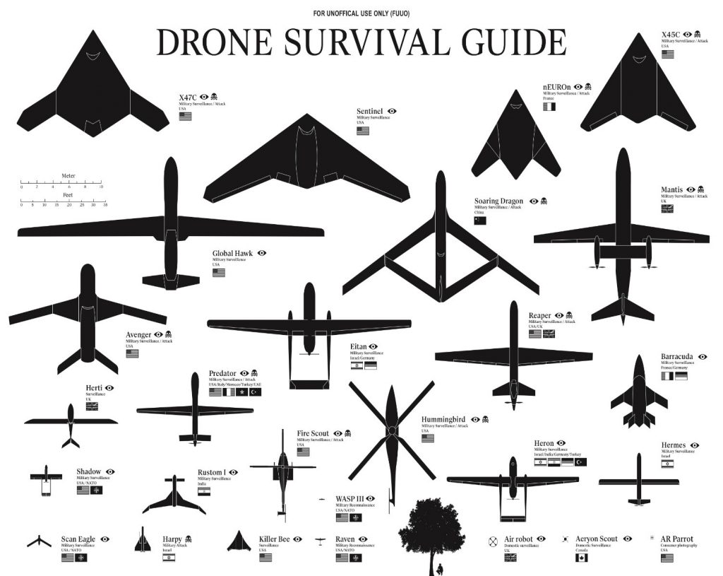
Source: Pater, R. (2018). Drone Survival Guide. Retrieved from http://www.drone.survivalguide.org/DSG.pdf
Remote sensing systems can be divided into two categories; active and passive. Active sensors emit EM radiation, directed at a target and then measure the reflected signal. (Marshall, 2016) Passive sensors do not emit EM radiation, instead measuring what is emitted by other sensors after it is reflected or as the target emits it. In UAS ARS the external target is almost always the sun.
The EMS is broken down into bands. EM bands are segments of energy grouped together by a common property and defined by a specific range of v It helps to understand the terminology: Agency for Science, Technology and Research (ASTRA) defines the following: VNIR = Visible light and near infrared (NIR) 400 – 1400 nm, 0.4 – 1.4 µm wavelength range (MIR); SWIR=Shortwave infrared, 1400-3000 nm, 1.4 -3.0 µm wavelength range; and TIR = Thermal infrared = 8000 – 15000 nm, 8 -15 µm (TIR) vibrational wavelengths. (Marshall, 2016) In ARS, the bands most commonly dealt with are in Table 7-1. (Schowengerdt, 2007)
Table 7-1 2007 Listing Remote Sensing Use of EMS
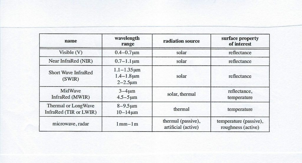
Source: (Schowengerdt, 2007)
Table 7-1 illustrates that different spectrums have various sources and different surface properties that are measured by wavelength. The imaging sensor responds to specific wavelength of incoming EM radiation. This response can be measured and calibrated. (Marshall, 2016) The calibration process is called radiometric calibration. Once a sensor is calibrated for a subset of the EMS, the sensor response can be linked directly to an individual component wavelength of the EMS being reflected by the target. (Marshall, 2016) Another powerful aspect of ARS is spatial continuity, which is the ability to know what is happening at a target location at every location surrounding the target for quite a distance. (Marshall, 2016)
Units
Since chapter wavelengths are referred to in SI units, Table 7-2 shows the common units used for EMS radiation bands.
Sensor Types
Two general types of ARS: Those that build images (Imaging sensors) and those that do not (spot sensors).
Spot sensors
Spot sensors measure single locations and do not create an image library. They do not facilitate special continuity, rather they opt for simplicity. (Marshall, 2016)
Table 7-2 Common Wavelengths units for Electromagnetic Radiation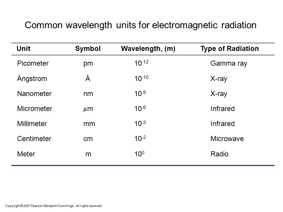
Source: (Cummings, 2007)
Imaging Sensors
There are three basic ways to generate images for an ARS: Line scanners (push- brooms) and array sensors. Line scanners move a single or small number of sensors elements back and forth to build up a picture of the target acquisition. It is limited by pivot distance, movement speed, and sensor processing time to build the image. Push-brooms have a fixed array of sensors, which are the width of the final image product across the A/C path, but only one element tall. Array sensors are like digital cameras, in that when triggered the entire array “flashes” simultaneously. (Marshall, 2016)
Camera
The most common UAS remote-sensor is the camera. There are four types of ARS cameras: Visible Spectrum, Near Infrared, Infrared and Hyperspectral. (Marshall, 2016)
Visible Spectrum Cameras (VIS) and Near-Infrared (NIR) Cameras
VIS and NIR cameras operate on the same principles, the only difference being the NIR camera sensor is sensitive to the NIR wavelengths (See Table 7-1). A VIS image consists of three primary colors, red, green, blue (RGB) to create a full color image. NIR images can capture green, red, and NIR reflectance. The human eye cannot see NIR. Therefore, the NIR band of colors is artificially shifted to form human-visible colors. The standard is called Color InfraRed (CIR). (Schowengerdt, 2007)
Long-Wave Infrared Cameras (LWIR)
LWIR sensors respond to heat striking the sensors. The temperature change causes an electronic signal to be generated. Bright spots or high heat flashes can wipe out the thermographic images. (Schowengerdt, 2007)
Infrared sensors beyond 1800 nm of the EM range can not use the same sensor materials as for VIS or NIR cameras. (Marshall, 2016) The concept of influx of radiation into a 2-D array of sensor element is the same. The physical and material properties of the LWIR camera receptors is different. Thermographic images can be created by cryogenic cooling of camera sensors. Another approach is to use room temperature sensors which have individually calibrated sensors reacting to incoming radiation.
Hyperspectral Images
Hyperspectral images use hundreds of color channels per image (not just the single RGB channel). The resulting image is called a Hyper Cube and multi-band image. Think of taking many pictures all at the same time and merging them. Problems for UAS use: prohibitive cost, vibration, requirement for stable Position and Orientation System (POS), power consumption, and weight. (Marshall, 2016)
LIDAR
Light Detection and Ranging (LIDAR) is the game changer for ARS. LIDAR uses a laser beam and a receiver to measure the distance to the ground. LIDAR sensor systems can discriminate between multiple return reflections of a single light pulse. (Marshall, 2016) Flash LIDAR is the recent evolution of technology which uses a single point source emission variant of previous versions using separate scanners and emitters. (Marshall, 2016) Research is close to having a Geiger mode LIDAR than can measure the return of a single photon. LIDAR systems require a very accurate measurement of time, sensor pointing angles, and sensor-spatial location. Efficiency decreases with height. Range is a function of UAS capabilities. (Marshall, 2016)
Synthetic Aperture Radar (SAR)
SAR systems are radar systems that map by using a band of EM spectrum in the range of 1 m -> 1mm. (Schowengerdt, 2007) SAR sends out a radar pulse and uses the reflected radar signal and the receivers motion to construct either a 2-D or 3-D image of the returning echoes. “The resolution can be as high as a few centimeters (depending on the wavelength used).” (McGlone, 2004)
Figure 7-2 SAR Imaging Geometry for Strip Mapping Option
Source: Schowengerdt, R.A. (2007) Remote Sensing (Third edition), Chapter 1: The Nature of Remote Sensing, 2007, Academic Press. 3 Available as 17 pp PDF at: http://www.springer.com/cda/content/document/cda_downloaddocument/9781461419938-c1.pdf
There are two other SAR options: ScanSAR mode and Spotlight. Figure 7-3 shows their relationship to Strip map mode.
Figure 7-3 SAR Modes of Operation
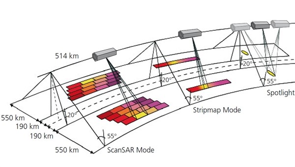
Source: DLR. The three SAR (Synthetic Aperture Radar) modes: Spotlight, Stripmap, and ScanSAR. Viewed September 11, 2018. https://www.dlr.de/dlr/en/desktopdefault.aspx/tabid-10382/570_read-431/
SAR is very computer intensive, uses long wavelengths that can pass through clouds, smoke, and dust in the atmosphere to produce a high spatial resolution that can pick up on surface features, such as waves and textures. (Marshall, 2016) See Figure 7-2 for an example of SAR RADAR geometry for strip mapping option.
Live Video Gimbals for VIS, MWIR and LWIR Cameras
Live streaming images from anywhere via drone cameras use a gimbaled system, which allows operation in a 360-degree arc. This allows continuous observation of a ground target. Many commercially manufactured gimbals are built for military use and ISR operations. Figure 7-4 shows a TASE 500 that works with VIR, MWIR and LWIR cameras.
Figure 7-4 shows a TASE 500 that works with VIR, MWIR and LWIR cameras.
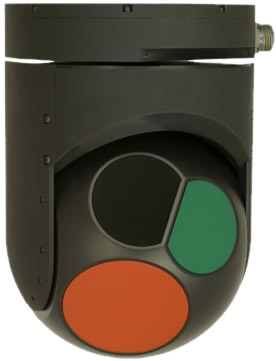
Source: UTC Aerospace Corporation. (summer, 2018). TASE 500 Gimbals fact sheet, http://www.cloudcaptech.com/images/uploads/documents/TASE500_Data_Sheet.pdf
Figure 7-5 Drone Jammer Model KWT-FZQ used for Police interception
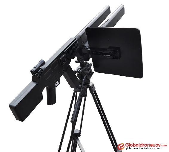
Source: GlobalDroneUAV.com (summer, 2018) Police drone jammer effective drone controller. https://globaldroneuav.com/Product/Police-drone-jammer-effective-drone-controller.html
Predicting Conflict
“Non-recreational UAS systems are used for DDD (Dull, Dangerous, and Dirty) missions. UAS deployment requires an ability to navigate in unknown territory, to avoid static obstacles, to avoid moving obstacles like airplanes, birds, intruder UAS, and anything else (missiles or a drone jammer).” (Kopřiva, 2012) Figure 7-5 looks at a Drone Jammer Gun Model KWT-FZQ used for Police interception.
Unless the frequency and range are right, drone jammers are not always successful.[2] UAS systems with special counter jamming modules can maneuver away to safety.[3] Military and commercial UAS systems must do their DDD work in any weather conditions, especially inclement. Military UAS systems must be able to detect “Identification Friend or Foe” (IFF) situations. Of special importance is a UAS near or in commercial controlled airspace. (Marshall, 2016) “The UAS must be able to Sense and Avoid (SAA) potential conflicts regarding air-traffic regulations.” (Kopřiva, 2012)
Collision Detection and Resolution (CDR) systems are the next generation automated SAA. (Marshall, 2016)They use many of the sensors described here. CDR systems for UAS were the product of ideas and engineering development “from airport management automated tools like the Traffic Collision Avoidance System (TCAS) (Anonymous, 2018) and the Precision Runway Monitor (PRM).” (Kopřiva, 2012) “Both systems are used to increase safety in the NAS and the mobility of air- traffic.” (Kopřiva, 2012) “A separate domain of investigation came from the robotics and AI research facilities.” Scientists studying these disciplines were interested in “trajectory planning and obstacle avoidance algorithms for aerial, ground, and maritime systems.” (Kopřiva, 2012) CDR has been investigated by several researchers; two of importance are Krozel, who presented a survey of CDR methods, and Albaker who concentrated on CDRs for UAVs.
Conflict Detection and Resolution Principles
Angelov defines “Conflict as an event in which the horizontal or vertical Euclidian distance between two aircrafts breaks the minimal defined separation criterion.” (Marshall, 2016) “The criterion varies based on the airspace the UAS is flying in and may be different for different UASs.” (Kopřiva, 2012) Recall Figure 3-2 Self -Separation and Collision Volume. (Marshall, 2016)
“The Safety Zone (SZ) is defined as the horizontal and vertical separation criteria which form a cylindrical airspace volume around the UAS. The UAS is centered in that volume. Safety Zone (SZ): defined as the horizontal and vertical separation criteria which form a cylindrical airspace volume around the UAS. In figure 3-2 that volume is defined by 1000 ft radius and 200 ft height. It is assumed that initially the UAS is in the center with 100 ft above and below the A/C. Under no circumstances may the SZ be violated by another UAS. For CDR systems different horizontal and vertical criteria may apply.” (Kopřiva, 2012)
Figure 3-2 Self -Separation and Collision Volume
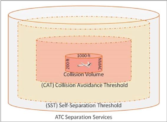
Source: Angelov, P. (2012). Sense and avoid in UAS research and applications. Hoboken: NJ.
CDR Architecture
The Conflict Detection and Resolution (CDR) architecture is simple. “It involves five processes:
- Sensors – Sensing for both Cooperative and Non-Cooperative A/C
- State Prediction – Trajectory predictions and results from Sensing stage
- Conflict Detection – Conflict as an event in which the horizontal or vertical Euclidian distance between two aircrafts breaks the minimal defined separation criterion. Conflict as an event in which the horizontal or vertical Euclidian distance between two aircrafts breaks the minimal defined separation criterion.
- Conflict Resolution – Determines / generates commands to pilot / autopilot
- Evasion and Maneuver – Move in predefined programmed ways including return to Waypoint.” (Kopřiva, 2012)
“The function of the CDR system is to detect a potential collision and provide the resolution in terms of an evasion maneuver which will be executed by the UAS’s autopilot.
The CDR block logic is simple.” (Kopřiva, 2012) The actual mathematics of predictions and models to elucidate these predictions to be carried out in real-time by the UAS autopilot are a totally different story.
Sensing
The subject of sensors and various technologies used was discussed early in this chapter. “Their purpose is to monitor the surrounding environments for both static and dynamic obstacles using the onboard systems. There are two distinct types of sensors of interest; cooperative and non-cooperative.” (Kopřiva, 2012)
Cooperative Sensors
“Cooperative sensors are those that receive radio signals from another aircraft using on board equipment.” (Zeitlin, 2012) “Cooperative sensors provide the ability to sense the environment and to communicate with aircrafts equipped with the same type of sensors by establishing a communications link.” (Kopřiva, 2012) The Automatic Dependent Surveillance Broadcast (ADS-B) is an example of a cooperative sensor. (Angelov, 2012) The ADS-B transfers longitude, latitude, altitude, speed, direction over ground, and unique UAS identification. Advanced cooperative sensors can transfer entire flight plan data and weather conditions. (Angelov, 2012)
Non-Cooperative Sensors
“Non-Cooperative Sensors sense the environment to gather information about obstacles and other aircraft or UAS.” (Kopřiva, 2012) There are no communications links to another aircraft or intruder UAS. “Sensor information needs to be processed to get the correct environment state knowledge.” (Kopřiva, 2012)
“Types of non-cooperative sensors include Inertial Measurement Unit (IMU), Laser Range Finders (LRF), Stereo Camera Systems (SCS), Single Moving Camera (SMC) and radar” Active radar is used on the larger UAS. SMC and SCS systems are used on the smaller UAS.” (Kopřiva, 2012)
Intruder Aircraft
What is an intruder aircraft? As seen in Figure 7-6, Bageshwar shows that an intruder aircraft is any aircraft that breaks the self-separation threshold, from any direction, not necessarily in the collision path of the UAS. (Bageshwar, 2015) Note the path of intruder, the potential collision point in space, the decisions and executable commands that must be processed in real time and the maintenance of the Collision Avoidance Threshold (CAT).
Non-cooperative aircraft miss some very good information. Consider the TCAS II. Figure 7-7 shows sample terminology of Traffic Alert (TA), Resolution Advisory (RA), Proximity Intruder Traffic (PIT) and Non-Threat Traffic (NTT) for specified criteria. (Anonymous, 2018) Figure 7-8 shows the TCAS II Conceptual framework. (Anonymous, 2018) Figure 7-9 shows what the pilot sees in his cockpit. Wikipedia has a worthwhile description of TCAS II, its operational modes, maneuver commands, TAs, RAs, configurations, and plenty of references.
Trajectory Prediction
“To detect and resolve a conflict, it is necessary to compare the trajectory of the UAS and the trajectory of the sensed object.” (Kopřiva, 2012)
The trajectory is produced by the trajectory computation unit from the raw sensor input data.
There are four basic models for trajectory prediction. “In the nominal method, the trajectory is predicted directly from the sensor data without considering any uncertainty of change.” (Kopřiva, 2012)
Figure 7-6 Intruder Aircraft and SAA Decisions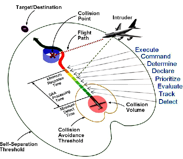
Source: Bageshwar, B. (2015). Multi-intruder aircraft, multi-sensor tracking system. 2015 IEEE/AIAA 34th Digital Avionics Systemes Conference (DASC).
Figure 7-7 TCAS II Terminology
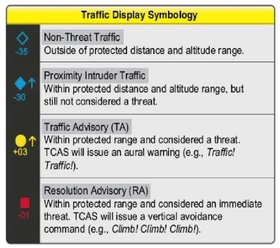
Source: Sanders T. (2017) QUORA, https://www.quora.com/If-a-plane-any-kind-is-not-equipped-with-TCAS-is-it-likely-to-collide-with-other-aircraft-over-oceans-when-there-is-no-radar-penetration
Figure 7-8 TCAS II Conceptual Framework
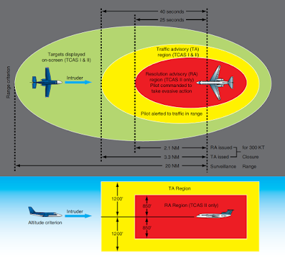
Source: Wijerathne, C.(2017). Collision Avoidance Systems, Aeronautics Guide. http://okigihan.blogspot.com/2017/05/collision-avoidance-systems.html
“The output of the nominal trajectory predictor a single trajectory computed from the last sensor scans.” (Kopřiva, 2012) This is very similar to boat navigators use of dead reckoning from last known positions determined by landmark or sky information.
Figure 7-9 TCASS II Cockpit View
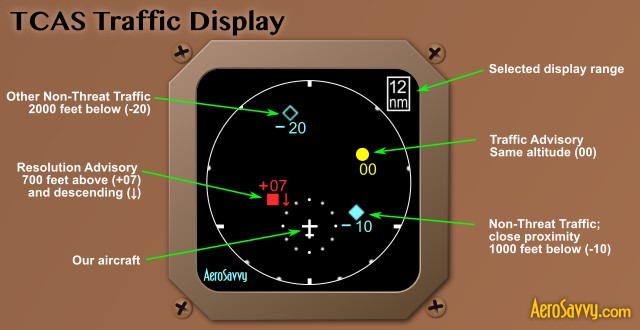
Source: AeroSavvy.com (2015) TCAS: Preventing Mid-Air Collisions. Aerosavvy, Aviation Insight. https://aerosavvy.com/tcas/
“The trajectory may be computed by various mathematical approaches; linear, non-linear, Taylor series, or Kalman filter. The nominal prediction is good for short- predictions, where probability of change is low. “ (Kopřiva, 2012)
“The worse-cast prediction covers the full range of maneuvers that an aircraft may perform and using a look-ahead time parameter computes the area where the aircraft may occur. This computed area is the predicted trajectory.” (Kopřiva, 2012)
“In the probabilistic prediction approach, the uncertainties are used to model the potential variations in the trajectory. All possible trajectories are generated, and each trajectory is evaluated by the probability function. This model is a trade-off between the nominal method and the worse-case method. Decisions are based on the likelihood of the conflict.” (Kopřiva, 2012)
“The flight plan approach works only with cooperative sensors. Intruder aircraft and home aircraft exchange flight plan data. The exact trajectory is known, and no predictions are required. The plans are exchanged as a set of way-points together with SZ parameters. The advantage of this model is the exact knowledge of the future trajectory. This model requires high bandwidth for the data transmission.” (Kopřiva, 2012)
Conflict Detection
“Conflict is detected based on the flight plan representation obtained from the trajectory prediction unit. The unit checks the flight plans (cooperating A/C) of both planes and checks whether the safety zone of any airplane has been violated. If so, then the parameters (position and times of possible conflict) are passed to the conflict resolution unit. Conflict detection can be expressed in 2D Horizontal Plane, 2D Vertical Plane or 3D display.” (Kopřiva, 2012)
Conflict Resolution
According to Kopriva, “there are eight methods that the conflict resolution modules use to avoid collisions: rule-based methods (RB), game theory methods (GT), field methods (F), geometric methods (G), numerical optimization methods (NO), combined methods (C), multi-agent methods (MA) and other methods (O).” (Kopřiva, 2012) C and O designations are not considered in this chapter.
- “Rule-based methods use a set of prescribed rules to avoid conflict. The sets of rules are fixed during the system design phase. This is a limited solution because it only works with planes in a shared air-space. This method does not permit changes or integration of further intentions. Little communication between planes is required.” (Kopřiva, 2012)
- “Game-theory methods (GT) use game theory to model the differential behavior of the two planes. GT is useful for non-cooperative conflict resolution for the short-term solution. Recall that non-cooperative sensing data which may be used for GT methods are generated from radar, laser range finders, stereo cameras, moving cameras, IR cameras and EO cameras.” (Kopřiva, 2012)
- “Field methods (F) treat each airplane as a charged particle and are very close to a reactive mechanism. The field is computed based on current configuration, state, positions of the airplanes, weather and other uncertainties. The UAS based on its own positional data in this field applies control actions depending on the state of the airplane with respect to the field. Evasive maneuvers are generated based on the repulsive forces between the field. Field methods are computer intensive.” (Kopřiva, 2012)
- “Geometric methods (G) Geometric methods are really limited to two planes in the CV. They solve an optimization objective function based on trial evasive maneuvers. Multi intruder planes present a complex sub-optimal problem solution, especially when changing parameters of altitude, velocity, and heading are factored in.” (Kopřiva, 2012)
- “Numerical optimization methods (NO) use a kinematic model of the aircraft along with a set of constraints and cost metrics to determine the best evasion maneuver.” These are formal, elegant solutions to the CR problem. However, the more intruder planes, the NO methods become intractable. “Defining the set of constraints becomes the real challenge for this method.” (Kopřiva, 2012)
- “Multi-agent methods (MA) use a multi-agent framework for solution generation. Each aircraft is controlled by one agent. The agents communicate. The agents negotiate the solution using various utility functions.” (Kopřiva, 2012)
Evasion Maneuvers
“The last stage in the decision model is evasion and maneuver. The output from the conflict resolution system/module is proposed evasion maneuvers to avoid conflict and collision. UAS have multiple maneuver options: speed-up, slow-down, keep the same speed, turn-left, turn-right, climb, and descend. Combined maneuvers are also possible, i.e. change speed while turning left.” (Kopřiva, 2012)
CDR Taxonomy
Angelov proposes a taxonomy for Collision Detection and Resolution System. His Figure 6.5 (Angelov, 2012) illustrates all the subgroups expressed in the previous paragraphs. In his Table 6.1 on the following page, he describes the attributes and abbreviations used for CDR classification broken down by the five classes in his taxonomy. (Angelov, 2012)
Discussion Questions
- Which one of the five CDR logic systems would be most susceptible to cyber-attacks and why?
- Propose a method to disrupt the trajectory predictions by 5% and which would report this error to the conflict detection stage.
- Research the maritime Automated Identification System for Collision Avoidance (AIS) system. Note the similarities to the TCAS II. Note also the GUI and information parameters are superior to TCAS II. Design / report on a CONOP to use the best elements and display of parameters of AIS to upgrade TCAS II to TCAS III
Bibliography
Angelov, P. (2012). Sense and avoid in UAS research and applications. Hoboken: NJ.
Bageshwar, B. a. (2015). Multi-intruder aircraft, multi-sensor tracking system. 2015 IEEE/AIAA 34th Digital Avionics Systemes Conference (DASC).
Cummings, B. (2007). Wikipedia Wavelength units images. Retrieved from Wikipedia: https://slideplayer.com/slide/8733356/
FAA Booklet Introduction to TCAS II Version 7.1.(2018) Retrieved from FAA: https://www.faa.gov/documentLibrary/media/Advisory_Circular/TCAS%20II%20V7.1%20Intro%20booklet.pdf
Kopřiva, S. Š. (2012). Sense and Avoid Concepts: Vehicle‐Based SAA Systems (Vehicle‐to‐Vehicle). In S. Š. Kopřiva, Sense and Avoid Concepts: Vehicle‐Based SAA Systems (Vehicle‐to‐Vehicle) (p. Chapter 6). Wiley Online Library. doi:https://doi.org/10.1002/9781119964049.ch6
Marshall, D. M. (2016). Introduction to Unmanned Aircraft Systems, 2nd Edition. New York: CRC Press.
McGlone, J. M. (2004). Manual of Photogrammetry (5th ed.). Bethesda, MD: The American Society for Photogrammetry and Remote Sensing.
Pater, R. (2018). Drone Survival Guide. Retrieved from Wikipedia: http://www.drone.survivalguide.org/DSG.pdf.)
Schowengerdt, R. (2007). Remote Sensing (Third edition). Retrieved from Chapter 1: The Nature of Remote Sensing: http://www.springer.com/cda/content/document/cda_downloaddocument/9781461419938-c1.pdf
Zeitlin, A. (2012, April 11). Performance Tradeoffs and the Development of Standards. Retrieved from Wiley Online Library: https://onlinelibrary.wiley.com/doi/abs/10.1002/9781119964049.ch2
Readings
Adamy, D. (2001) EW 101 A First Course in Electronic Warfare, Boston: Artech House.
Adamy, D. (2004) EW 102 A Second Course in Electronic Warfare, Boston: Artech House.
Adamy, D. (2009) EW 103 Tactical Battlefield Communications Electronic Warfare, Boston: Artech House.
Adamy, D. (2015) EW 104 EW against a New Generation of Threats, Boston: Artech House.
Adamy, D. (2003) Introduction to Electronic Warfare Modelling and Simulation, Boston: Artech House.
Albaker, B. & Rahim, N. (2009) A Survey of collision approaches for unmanned aerial vehicles, Technical Postgraduates (TECHPOS), 2009 International Conference for.
Angelov, P. (2012). Sense and avoid in UAS research and applications. Hoboken, N.J.: Wiley.
Austin, R. (2010) UAVS Design, Development and Deployment, New York: Wiley.
Barnhart, R.K., Hottman, S.B, Marshall D.M., and Shappee, E. (2012) Introduction to Unmanned Aircraft Systems. New York: CRC Press.
Burch, D. (205) RADAR for Mariners. New York, McGraw-Hill.
Drone Jammer Model KWT-FZQ: GlobalDroneUAV.com (summer, 2018) Police drone jammer effective drone controller. https://globaldroneuav.com/Product/Police-drone-jammer-effective-drone-controller.html
FAA Booklet: Introduction to TCAS II Version 7.1, (2018) see: https://www.faa.gov/documentLibrary/media/Advisory_Circular/TCAS%20II%20V7.1%20Intro%20booklet.pdf
Gall, D. (2017)QUORA: https://www.quora.com/If-a-plane-any-kind-is-not-equipped-with-TCAS-is-it-likely-to-collide-with-other-aircraft-over-oceans-when-there-is-no-radar-penetration
Gelbart, A., Redman, B.C, Light, R.S., Schwartzlow, C.A., and Griffis, A.J. (2002) Flash LIDAR based on multiple-slit streak tube imaging. LIDAR VII. Laser Radar Technology and Applications 4723, pp 9-18.
Hubbard, R. K (1998) Boater’s Bowditch, Camden, MA: International Marine.
Krozel, J., Peters, M., & Hunter, G. (April 1997) Conflict detection and resolution for future air transportation, Technical Report NASA CR-97-205944.
Monahan, K (2004) The RADAR Book: Effective Navigation and Collision Avoidance. Anacortes, WA: Fineedge Publications.
SAR Images: https://crisp.nus.edu.sg/~research/tutorial/mw.htm
SAR: https://www.dlr.de/dlr/en/desktopdefault.aspx/tabid-10382/570_read-431/
Schowengerdt, R.A. (2007) Remote Sensing (Third edition), Chapter 1: The Nature of Remote Sensing, 2007, Academic Press. 3 Available as 17 pp PDF at http://www.springer.com/cda/content/document/cda_downloaddocument/9781461419938-c1.pdf
Staff (2015) Camera. In Merriam Webster’s Online Dictionary. http://www.merriam-webster.com/dictionary/camera
Staff (2015) In situ. In Merriam Webster’s Online Dictionary. http://www.merriam-webster.com/dictionary/in%20situ
TASE 500 Gimbals: https://www.sypaq.com.au/sensorsandsurveillance/tase-gimbals/
TCAS Cockpit view: AeroSavvy.com (2015) TCAS: Preventing Mid-Air Collisions. Aerosavvy, Aviation Insight. https://aerosavvy.com/tcas/
Toomay, J.C. (1982) RADAR for the Non – Specialist. London; Lifetime Learning Publications
Traffic CA system, https://en.wikipedia.org/wiki/Traffic_collision_avoidance_system
Wavelength units images, Benjamin -Cummings (2007) and https://slideplayer.com/slide/8733356/
- In situ comes from Latin “in place” Merriam Webster’s Dictionary defines it as “in the natural or original position or place.” ↵
- https://www.youtube.com/watch?v=2Bqj0bkSJWE ↵
- GlobalDroneUAV.com (summer, 2018) Police drone jammer effective drone controller. https://globaldroneuav.com/Product/Police-drone-jammer-effective-drone-controller.html ↵
