17 Wireless Power for Space Applications [Khan]
EXECUTIVE SUMMARY
Nearfield wireless power transfer (WPT) systems can benefit satellites having either standard or functional-modular architecture because of their high efficiency when compared to a laser or microwave system. A practicable wireless power transfer (WPT) system needs to maintain high transfer efficiencies while containing electric and magnetic near fields for wireless satellite power applications. Nodes that do not have shielding can become susceptible to electromagnetic interference (EMI) both as a source and as a receiver. One way to deal with this problem is to mitigate lateral emission in the unprotected zone between transmitter and receiver. Early results show chiral ordering of a 4-tier WPT system can limit the unprotected lateral emissions by beam shaping in the zone between transmitter and receiver during the charging process.
Keywords— Helical antennas, parasitic elements, wireless power transfer (WPT), near field, chirality, frequency selective surfaces (FSS), satellite systems
INTRODUCTION
WPT systems can bring certain advantages to satellite systems having different architectures. Satellite wireless buses help reduce cabling weight. To reduce EMI interference, while maintaining efficient power transfer in a crowded field of electronic devices, one needs the near field shaping capability discussed here. The chapter begins with a general discussion of WPT options and moves quickly on to the design and research conducted of a system capable of beam shaping while maintaining high efficiency.
BASICS OF WPT SYSTEMS
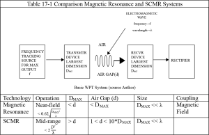
WPT systems can be classified as near-field, mid-range, or far-field based on coupling distance (Triviño-Cabrera et al., 2020). In near-field operation can be inductive or capacitive. Inductive systems can be further broken down into magnetic resonant or non-resonant. In mid-range operation WPT systems use strongly coupled magnetic resonant system (SCMR) which is similar to the resonant inductive systems but has greater range generally achieved by adding parasitic components to the coupling system. Far-field systems such as optical and microwave systems have low efficiencies and require a larger payload volume and are therefore not suitable for satellite deployment (Zhang et al., 2019). Our chosen application lies between magnetic resonant and SCMR systems Table 17-1 compares these two technologies based on frequency of operation (f), wavelength(λ), and largest dimension of coupling device (DMAX≈d).
Table 17-1 Comparison Magnetic Resonance and SCMR Systems
MOTIVATION
Depending on the architecture of the satellite system(s) WPT technologies can provide better immunity to EMI and reduced weight from not using cabling. In a traditional architecture it can be used to transfer power from solar panels to a receiver while in a modular spacecraft WPT can be used to provide power between the modules. Our designed system has the ability to shape near fields which is critical to avoiding EMI interference in satellites and can help reduce losses.
NEAR FIELD SHAPING
The primary goal of this research has been to limit near-field emissions for an efficient resonant WPT system (Karalis et al., 2008; Kurs et al., 2007) i.e. to optimize transfer efficiency while keeping human safety in mind. More specifically, our paper would like to further expand on early results that show, chiral ordering of a 4-tier WPT system can limit the unprotected lateral emissions in the zone between transmitter and receiver (Khan, Saeed & Bailey, Chad, 2021).
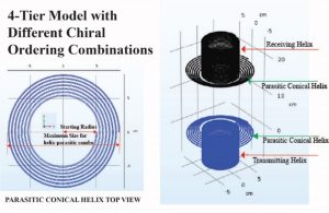
The 4-tier system (Figure 17-1) is composed of chiral objects that are right-hand (RH) or left-hand (LH). Both the helical transmitter and receiver can be considered to be chiral metaparticles (Caloz & Sihvola, 2020), i.e. it has a length close to half a wavelength and a height that is much smaller than its length. The parasitic elements are RH or LH chiral objects but do not necessarily meet the length requirements for metaparticles. With sixteen possible arrangements are possible, the research will focus on two arrangements holding the most promise from the perspective of field containment and efficiency. We assume that shielding (Wang, Zuming & et. al., 2021) can be employed in other zones that do not impede the path of direct energy transfer which is further clarified in the section on background.
Figure 17-1 4-Tier WPT system where the chirality of helices and parasitic elements are ordered in different combinations of right-hand and left-hand chirality
Source: Author
EARLY RESULTS
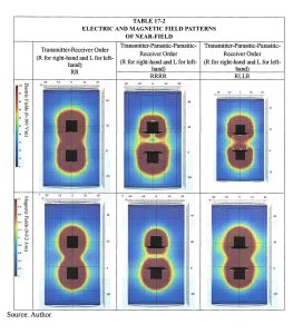
Table 17-2 shows impact on field containment happening in the unprotected area between transmitter and receiver (Note: RRRR indicates for four-tier system components are all right-handed; RLLR indicates only parasitic elements are left-handed). Figure 17-3 shows field closer view of a system where all tiers are right-hand. Also, efficiencies of the WPT system depend on the- chirality (right/left hand) order of the system (Table 17-2). Proper ordering can lead to 70-80+% measured efficiencies for distances of 5-20 cm. Higher efficiencies (90%+) have been recorded through COMSOL simulations without accounting for measurement setup losses. Resonant frequencies of the system have also been shown to depend on the chirality order of the four-tier system. Frequency tracking capability is assumed (Chaidee et al., 2017; Liu et al., 2018; Nam Yoon Kim et al., 2012).
The paper describes the work of a four-tier (transmitter-parasitic element-parasitic element-receiver) resonant WPT system consisting of two helical antennas each with a conical helix serving as a parasitic element. It focuses on E-field and H-field containment at high efficiencies through simulation and experimental work. Based on the novel work (Khan, Saeed & Bailey, Chad, 2021) performed, there is a good possibility this investigation will lead to a safe and efficient near-field transfer systems.
BACKGROUND
The successful design of a system that can safely transfer 100 kW or more of power over a 100-200 mm gap under varying conditions of humidity, while maintaining high efficiencies, is a challenge for any person or team. Effective implementation of the above specifications will be rewarded with a resonant (Kurs et al., 2007; Barman et al., 2015) wireless power transfer system (WPT) that can support the charging of devices such as electric vehicles (EIVs), drones (UAVs), and robots (UGVs) comfortably, even with the current state of storage technology. In addition, a good wireless charger (Ahmad et al., 2018; Chittoor et al., 2021) is expected to enable interoperability with a large tolerance for misalignment while meeting safety requirements.
The basic structure of the proposed system (Figure 17-1) consists of a center-fed transmitting normal mode helical antenna (NMHA) and an identical receiving NMHA helix loaded at the center (Imura et al., 2009). Multiturn-helical antennas form efficient WPT systems (Barman et al., 2015; Imura et al., 2009) and while NMHA mode requires the helix to be electrically small in height the overall length, using multiple turns, it can be made to be about half a wavelength to qualify as a chiral metaparticle (Caloz & Sihvola, 2020). The parasitic elements are conical helices which are at their minimum radius flush with the side facing the transfer gap.
The use of parasitic elements in the structure is supported partially supported by the work by Andre Kurs et al (Kurs et al., 2007) where efficient indirect WPT was reported between self-resonant transmitter and receiver coils by way of using a feeder loop and loaded receiver loop. In another case, work done by K. Firdaus et al shows (Firdaus et al., 2015) that a spiral slot with length comparable to half a wavelength has good transmission characteristics when placed between two identical right-handed helical antennas in a WPT system where the transmitting helix and receiving helix are equidistant from the slot. The choice of 3-D chiral metaparticles as parasitic elements seems to be the next step from placing planar objects between receiving and transmitting helices, which have demonstrated a positive impact on coupling. Indeed, the parasitic elements in our design are 3-D version of an achiral Archimedean spiral forming a chiral conical helix.
ANALYSIS OF PRELIMINARY RESULTS
Of the total sixteen possible 4-tier chirality orders eight can be considered to be equivalent to the other eight e.g., RLLR is the chiral equivalent of LRRL. Measurements and simulations were run on eight structures of which two (RRRR & RLLR) were found promising in terms of their efficiency (Figure 17-4). Note: Both measurements and simulation results account for cable and connector losses. Comparing measured (with PVC cylinder for alignment) and simulated (without PVC cylinder) has a mean efficiency difference of 5%.
Table 17-2 -FIX shows impact on field containment happening in the unprotected area between transmitter and receiver (Note: RRRR indicates for four-tier system components are all right-handed; RLLR indicates only parasitic elements are left-handed).
Source: Author
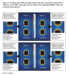
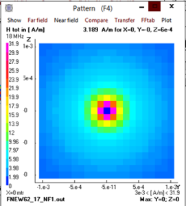
These structures were also examined for their ability to control lateral emissions in the unprotected zone. Simulation results from Table 1 compares two different 4-tier WPT chiral arrangements with a 2-tier one that does not employ parasitic elements. From inspection, both RRRR and RLLR ordered systems provide better electric field containment in the unprotected zone when compared to a system operating without parasitic elements (RR). The RRRR order provides the best containment for the magnetic field. Figure 17-2 provides a closer look at both the E-field and H-field containment by the RRRR arrangement.
Figure 17-2 H-Field and E-Field near field studies
.Figure 17-2 provides a closer look at both the E-field and H-field containment by the RRRR arrangement.
Source: Author
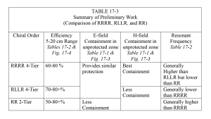
Table 17-3 summarizes and compares RRRR and RLLR systems with a 2-tier RR system from observations made from Table 17-2 and Figures 17-3 and 17-4. Table 17-3 also provides us with a possible task list that could lead to better understanding of the difference in efficiencies, field-containment, and resonant frequencies (Figure 17-5), that occur for chiral ordering of the WPT systems.
Figure 17-3 Transfer Efficiencies in % for different 4-Tier Arrangements.
Best results are indicated for RRRR and RLLR arrangements

Source: Author
Figure 17-4 Resonances for different chiral orders
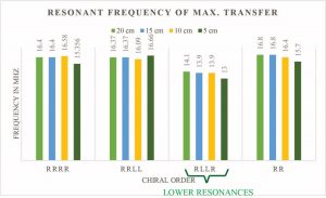
Source: Author
Table 17-3 summarizes and compares RRRR and RLLR systems with a 2-tier RR system from observations
Source: Author
Table 17-3 summarizes and compares RRRR and RLLR systems with a 2-tier RR system from observations made from Tables 17-1 & 17-2 and Figures 17-3 and 17-4. Table 17-3 also provides us with a possible task list that could lead to better understanding of the difference in efficiencies, field-containment, and resonant frequencies (Figure 17-5), that occur for chiral ordering of the WPT systems.
EXPERIMENTAL METHODS
Measurement of Efficiency and Unprotected Fields:
- 1 Introduction: WPT efficiency measurement has so far been conducted using a network analyzer using S-parameters and compared with simulation data while the study field emissions in the unprotected zone has been performed only through simulation. The purpose of this task is to design a Faraday cage experiment that measures both transfer efficiency and emissions in the unprotected zone for small amounts of power.
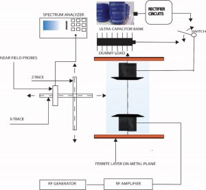
- 2 Measurement Setup Design: Figure 17-5 shows schematic for how both efficiency and unprotected zone emissions are to be measured (Chakarothai et al., 2018). The design has been adapted from previous instrumentation (Figure 8) setup for measuring near-field transfer efficiencies for helical antennas (Khan & Maresch, 2013a) and includes the ability to measure lateral emissions.
- 2.1 Measurement of Efficiency: The switch (Figure 17-5 ) should be connected to the power management system and a rectifier circuit while trying to find the efficiency of the WPT system. The following assumptions can be made during the process,
- The placement of the ferrite sheets does not significantly impact efficiency. Simulations run with and without this metal backed sheets seem to back up this assumption.
- The matching circuits of the rectifier system can be fine-tuned to the frequency of maximum transfer.
- The amount of transfer time is chosen such that the charging does not exceed the storage capacity of the ultracapacitor bank.
Like most modern battery chemistries, ultracapacitors require balancing if placed in series. This prevents the overcharging of one or more individual capacitors in a series string, which would cause a failure due to the breakdown of the dielectric material. Balancing, therefore, adds extra circuitry, and with-it inefficiencies, which could be avoided if the capacitors were placed in parallel. For this reason, and since capacitors add when in parallel, the prototype initially used a bank of parallel capacitors in series with a battery. Previous testing resulted in longer than expected charging times. This was due to the RC time constant, as the DC resistance of the circuit significantly contributes. Future designs will use series capacitors with balancing circuitry, or some series/parallel combination.
Figure 17-5 Proposed Measurement Setup For Measuring WPT Efficiency And Lateral Emissions
Source: Author
- 2.2 Measurement of Near-Fields: For this measurement the switch should be connected to the dummy load with about 200 W dissipation capability. The following points can be made for this measurement:
- The x-track (Figure 17-5) H-field and E-field measurements are going to be made adjacent to the WPT system in a horizontal line midway between receiving and transmitting antenna. Based on simulation results the fields should die off rapidly in this zone.
- The z-track field measurement will also take place in a vertical line adjacent to the WPT system.
- Both electric and magnetic probes can be adjusted for x, y, and z, field measurements.
Figure 17-6 Previously used instrumentation for efficiency measurement. Clockwise from left, adjustable stand, transmitter cart, receiving antenna. An adjustable height test stand supports a breadboarded power management circuit and a receiving antenna, suspending it above a transmitter cart/antenna at set distances
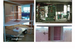
Source: Author
- 2.3 Expected Outcomes:
- Characterization of coupling efficiency measurements using low power source (up to 13 dBm) for separation distances of 5-20 cm using network analyzer.
- Characterization of coupling efficiency measurements using higher power source (50-100 W) for separation distances of 5-20 cm inside Faraday cage.
- E-field and H-field measurements in an XZ plane close and adjacent to the WPT systems for different power levels.
From the list above items I-II will enable us to judge the impact on efficiency with/without a rectifier and power management system included. Item III will characterize the field penetration in the unprotected zone.
- 3 Potential Problems and Alternative Approaches: The expected outcomes (I & II) which relate to efficiency measurements are unlikely to run into problems given prior experience in the required setups. While the design for near field measurements (outcome III) will certainly require careful planning and proper orientation of both electric and magnetic probes, the data is being gathered in a zone adjacent to the WPT system that is unlikely to impact power transfer. While some re-design may be needed for field measurements the results should be corroborated by simulation.
2 Study of Field Containment and Chiral Ordering:
2.1 Introduction: The importance of field containment has been discussed in prior sections. This task can focus on understanding the phenomenon by which parasitic conical helices are able to minimize field penetration in the unprotected zone which is defined as the lateral shielded zone between transmitter and receiver.
- 2 Study of Simulated and Measured Data: The data gathered in Task 1 will be critical in establishing the field containment patterns from simulation by making experimental measurements. Relationships between field penetration, coupling distance and the frequency of maximum coupling are to be analyzed in this study. Initial studies conducted already indicate that the resonant frequency is lowered by 4-tier RLLR systems when compared to RRRR arrangements and 2-tier RR systems (Table. 3) and leads to the following questions,
- Why is there a difference in resonant frequency between RLLR and RRRR systems that have the same size?
- Is it possible that the parasitic elements in RLLR couple more strongly with the active elements than in the RRRR case as the lowering of resonant frequency might suggest?
- What explains the better magnetic field containment in the RRRR case when compared with the RLLR case (as indicated by simulation results in Table. 1)?
- Why do both RRRR and RLLR have similar containment for the electric field?
- What role does chirality order play in questions I-IV?
The answers to questions I-V will help develop an understanding of the mechanism of field containment using WPT systems using chiral ordering leading to a more efficient and safe design.
- 3 Study of Semi-analytical Approach: The approach taken thus far has relied on experimental measurements and simulation results, another approach might be to take a semi-analytical route. More specifically, explain the reason for differences in resonant frequency by studying coupling between the antenna and its parasitic element on the receiver side (I-II sec 2.2). Work done in calculating the mutual impedance of a dipole and a parasitic element suggests the proposed approach.
Questions I-III from the previous section can be better understood by calculating mutual impedance between the transmitting dipole and the near parasitic element. The higher resonant frequencies imply less coupling in the RRRR case and is a likely cause of narrower beam, but this can be investigated further by calculating the mutual impedance of a dipole and a parasitic element suggests a semi-analytical approach can be useful in this process.
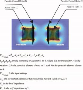
Using a similar process (Visser & Lulu Chan, 2014) for near field WPT employing parasitic elements and an active receiver and transmitter dipole for our design. It is possible to calculate the impedances Z11, Z12, Z13, and Z14, by using 4 different values of ZL using simulation to provide for I1, I2, I3, and I4 for each of the load impedances (Figure 17-7). The currents can be determined by simulation results using (using 4Nec2) and then the results can be verified by experimental means using accessible ports. It is expected that the value of Z12 will provide clarity to beam shaping and resonant frequency differences discussed earlier for RRRR and RLLR. Experimental results conducted thus far seems to indicate lower levels of coupling between the transmitter and its nearest parasitic element (Z12) from relatively higher resonant frequency in RRRR case.
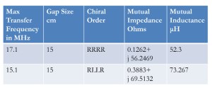
Some initial results using the semi-analytical is provided below (Figure 17-8-9) using the technique described in the previous section. These results indicate that RLLR (ZM= 6951Ω) is more strongly coupled than the RRRR (ZM= 5619 Ω) 4-Tier structure at no load condition and possesses a lower resonant frequency and the receiver voltage (V1) is higher assuming Z11=Z22 for the identical antennas. This approach needs to be further examined using a loaded condition.
Figure 17-7 Relationship Between Self-Impedance, Mutual Impedances, Load Impedance, Currents, And Applied Voltage
Source: Author
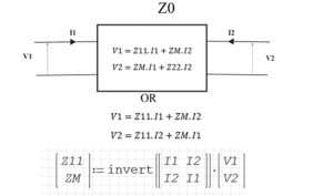
Figure 17-8 Equations For Finding Coupling Using Simulated Or Measured Results
Source: Author
Figure 17-9 Mutual Inductance Calculated With Semi-Analytical Approach
Source: Author
- 4 Expected Outcomes: A better understanding of these important questions (sec. 2.2) will help design safe and efficient near field WPT systems i.e., a better understanding of chiral layering in near field coupling and how this 4-tiered systems impacts field containment and resonant frequencies.
- 5 Potential Problems and Alternative Approaches: Measurements added by Task 1 will enhance our understanding of the questions posed in section 2.2. The approach takes a deeper dive into these questions from section 2.3 in and the calculation of mutual impedance between transmitting dipole and its parasitic element using similar technique used for dipoles (Visser & Lulu Chan, 2014).
FUTURE WORK
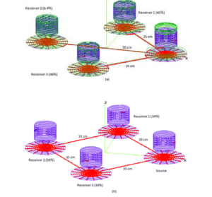
A past research endeavor (Khan, 2017, 2019; Khan & Maresch, 2013b) regarding resonators connected to the same ground plane (Saeed Khan et. al., 2018) indicates the possibility that multiple devices can share wireless power from the same receiver without rectification at the transfer frequency (Figure 17-10). This will allow the advantage of using different power management systems within the payload i.e. if power can be transferred from one receiver to several others without the need for rectification and DC conversion.
Between the two configurations of single source multi-receiver architecture (Figure 17-10) the coupling between the source and any receiver is seen to depend on the distance and is proportional to as would be expected in the near field region of a radiator.
A point of interest is in the connecting wires between ground planes. As seen in Figure 17-11 the thin connecting wires behave as a single wire WPT line where the magnetic field seems to be contained. Also, these wires are less likely to get impacted by EMI when exposed to impinging electrons and ions on the satellites in orbit.
Figure 17-10 From a single WPT receiver Nec4 simulation shows system (a) and (b) are operating at almost 100% efficiency. All receivers are within the same near-field zone of the source
Source: Author
Another future research objective is to study the impact of using frequency selective (Bresciani et al., 1992; Kuse et al., 2015; Luo et al., 2015; Mandal et al., 2020; Marhefka et al., 2007; Xing et al., 2020) surfaces (FSS) as ground connectors specially designed to immunize against unwanted frequencies for an orbiting space vehicle.
Figure 17-11 Magnetic Field Containment Within Connecting Wire
Source: Author
SUMMARY
It has been shown that WPT with beam shaping can deliver EMI immunity and beam shaping with our design. We began by describing how parasitic elements can help achieve high efficiencies and beam containment by proper layering based on chirality of a 4-tier system using both measured results and simulations. A semi-analytical approach was then used to gage the impact of parasitic components both from the resonant frequency and mutual coupling point of view.
We discussed the WPT systems that deploy connected ground planes in a single source multi-receiver system. The simulation (Figure 17-10) demonstrates that configuration is also a near-field technique since the coupled power to loads vary as 1/(distance)3 which agrees antenna theory. The application of this system can be used to transfer power throughout the entire satellite and therefore a good target for future work. Some of the research can be focused on ground plane connections using frequency selective surfaces (FSS).
ACKNOWLEDGEMENT
The author wishes to thank Chad Bailey, Instructor for the Electronic and Computer Engineering Technology (ECET) program Kansas State University Aerospace and Technology campus for his help with instrumentation, and measurement related to this work.
REFERENCES
Ahmad, A., Alam, M. S., & Chabaan, R. (2018). A Comprehensive Review of Wireless Charging Technologies for Electric Vehicles. IEEE Transactions on Transportation Electrification, 4(1), 38–63. https://doi.org/10.1109/TTE.2017.2771619
Barman, S. D., Reza, A. W., Kumar, N., Karim, Md. E., & Munir, A. B. (2015). Wireless powering by magnetic resonant coupling: Recent trends in wireless power transfer system and its applications. Renewable and Sustainable Energy Reviews, 51, 1525–1552. https://doi.org/10.1016/j.rser.2015.07.031
Bresciani, D., Cosentino, S., & Mantica, P. G. (1992). Inductive FSS for ground station applications. IEEE Antennas and Propagation Society International Symposium 1992 Digest, 1787–1790 vol.4. https://doi.org/10.1109/APS.1992.221503
Caloz, C., & Sihvola, A. (2020). Electromagnetic Chirality, Part 1: The Microscopic Perspective [Electromagnetic Perspectives]. IEEE Antennas and Propagation Magazine, 62(1), 58–71. https://doi.org/10.1109/MAP.2019.2955698
Chaidee, E., Sangswang, A., Naetiladdanon, S., & Mujjalinvimut, E. (2017). Maximum output power tracking for wireless power transfer system using impedance tuning. IECON 2017 – 43rd Annual Conference of the IEEE Industrial Electronics Society, 6961–6966. https://doi.org/10.1109/IECON.2017.8217217
Chakarothai, J., Wake, K., Arima, T., Watanabe, S., & Uno, T. (2018). Exposure Evaluation of an Actual Wireless Power Transfer System for an Electric Vehicle With Near-Field Measurement. IEEE Transactions on Microwave Theory and Techniques, 66(3), 1543–1552. https://doi.org/10.1109/TMTT.2017.2748949
Chittoor, P. K., Chokkalingam, B., & Mihet-Popa, L. (2021). A Review on UAV Wireless Charging: Fundamentals, Applications, Charging Techniques and Standards. IEEE Access, 9, 69235–69266. https://doi.org/10.1109/ACCESS.2021.3077041
Firdaus, K., Sakakibara, K., Amano, Y., Hirayama, H., Kikuma, N., Tabata, T., & Kojima, S. H. (2015). Design of spiral-slot frequency selective surfaces for shielding from noises of wireless power transfer. 2015 International Workshop on Antenna Technology (IWAT), 345–347. https://doi.org/10.1109/IWAT.2015.7365280
Imura, T., Okabe, H., & Hori, Y. (2009). Basic experimental study on helical antennas of wireless power transfer for Electric Vehicles by using magnetic resonant couplings. 2009 IEEE Vehicle Power and Propulsion Conference, 936–940. https://doi.org/10.1109/VPPC.2009.5289747
Karalis, A., Joannopoulos, J. D., & Soljačić, M. (2008). Efficient wireless non-radiative mid-range energy transfer. Annals of Physics, 323(1), 34–48. https://doi.org/10.1016/j.aop.2007.04.017
Khan, S. M. (2017). Analysis of wireless power transfer (WPT) scheme with connected ground planes. 2017 USNC-URSI Radio Science Meeting (Joint with AP-S Symposium), 21–22. https://doi.org/10.1109/USNC-URSI.2017.8074877
Khan, S. M. (2019). Practical Considerations for Resonant Near Field Wireless Power Transfer over Common Ground. 2019 USNC-URSI Radio Science Meeting (Joint with AP-S Symposium), 75–76. https://doi.org/10.1109/USNC-URSI.2019.8861832
Khan, S. M., & Maresch, N. D. (2013a). Near field wireless power transfer (WPT) between helical antennas under different conditions of orientation and ground plane construction. 2013 USNC-URSI Radio Science Meeting (Joint with AP-S Symposium), 116–116. https://doi.org/10.1109/USNC-URSI.2013.6715422
Khan, S. M., & Maresch, N. D. (2013b). Near field wireless power transfer (WPT) between helical antennas under different conditions of orientation and ground plane construction. 2013 USNC-URSI Radio Science Meeting (Joint with AP-S Symposium), 116–116. https://doi.org/10.1109/USNC-URSI.2013.6715422
Khan, Saeed, & Bailey, Chad. (2021). Efficient Wireless Power Transfer (WPT) and Field Containment Through Chiral Ordering of a Four-Tier WPT System. 2021 IEEE International Symposium on Antennas and Propagation and North American Radio Science Meeting, 9–10.
Kurs, A., Karalis, A., Moffatt, R., Joannopoulos, J. D., Fisher, P., & Soljacic, M. (2007). Wireless Power Transfer via Strongly Coupled Magnetic Resonances. Science, 317(5834), 83–86. https://doi.org/10.1126/science.1143254
Kuse, R., Hori, T., & Fujimoto, M. (2015). Filtering characteristics of FSS for realizing perfect magnetic conductor without frequency dependence. 2015 International Workshop on Antenna Technology (IWAT), 194–195. https://doi.org/10.1109/IWAT.2015.7365371
Liu, S., Shen, Y., Wu, Y., Lin, J., & Hu, M. (2018). Study on frequency tracking for wireless power transfer system using magnetic resonant coupling. 2018 13th IEEE Conference on Industrial Electronics and Applications (ICIEA), 2569–2572. https://doi.org/10.1109/ICIEA.2017-8398144
Luo, H., Wu, W., Meng, T., Huang, J., & Yuan, N. (2015). An absorptive/transmissive FSS radome with lumped resistors loaded. 2015 IEEE Advanced Information Technology, Electronic and Automation Control Conference (IAEAC), 494–497. https://doi.org/10.1109/IAEAC.2015.7428602
Mandal, B., Chatterjee, A., Rangaiah, P., Perez, M. D., & Augustine, R. (2020). A Low Profile Button Antenna with Back Radiation Reduced By FSS. 2020 14th European Conference on Antennas and Propagation (EuCAP), 1–5. https://doi.org/10.23919/EuCAP48036.2020.9135328
Marhefka, R. J., Young, J. D., & Towle, J. P. (2007). Design, fabrication and measurement of an FSS antenna ground plane. 2007 IEEE Antennas and Propagation Society International Symposium, 3972–3975. https://doi.org/10.1109/APS.2007.4396410
Nam Yoon Kim, Ki Young Kim, Young-Ho Ryu, Jinsung Choi, Dong-Zo Kim, Changwook Yoon, Yun-Kwon Park, & Sangwook Kwon. (2012). Automated adaptive frequency tracking system for efficient mid-range wireless power transfer via magnetic resonance coupling. 2012 42nd European Microwave Conference, 221–224. https://doi.org/10.23919/EuMC.2012.6459399
Saeed Khan et. al. (2018). Helical antenna wireless power transfer system (Patent No. US10050475B2). https://patents.google.com/patent/US10050475B2/en
Triviño-Cabrera, A., González-González, J. M., & Aguado, J. A. (2020). Wireless Power Transfer for Electric Vehicles: Foundations and Design Approach. Springer International Publishing. https://doi.org/10.1007/978-3-030-26706-3
Visser, H. J. & Lulu Chan. (2014). Active dipole coupling in an array environment. 2014 Loughborough Antennas and Propagation Conference (LAPC), 285–288. https://doi.org/10.1109/LAPC.2014.6996377
Wang, Zuming, & et. al. (2021). Wireless Charging Shielding Structure with Periodic Slots in UAVs for Weigh Reduction. 2021 IEEE International Symposium on Antennas and Propagation and North American Radio Science Meeting, 11–12.
Xing, Z., Yang, F., Yang, P., Yang, J., & Jiang, C. (2020). A Novel High-Performance FSS-AMC Radome Unit. 2020 IEEE International Symposium on Antennas and Propagation and North American Radio Science Meeting, 777–778. https://doi.org/10.1109/IEEECONF35879.2020.9329852
Zhang, L., Wang, L., Yu, H., Zong, Y., Zhang, Y., Ming, X., & Zhang, Z. (2019). Research on Wireless Power Transfer in Modular Spacecraft. 2019 IEEE Wireless Power Transfer Conference (WPTC), 470–474. https://doi.org/10.1109/WPTC45513.2019.9055628
