15 Strategy and Economics of Space Missions [Jackson & Joseph]
STUDENT LEARNING OBJECTIVES
- To understand the principles of manufacturing in space
- To understand space systems for the manufacturing mission
- To understand the economics of space missions and strategies
INTRODUCTION
Manufacturing in space is a strategic endeavor that produces materials that cannot be manufactured on Earth and where processing is affected by Earth’s environment. The advantages of manufacturing in space include operating in microgravity and vacuum, extracting high-value minerals from other planetary bodies or asteroids, and processing in low-Earth orbits before returning to Earth. Space missions established science-based manufacturing in space by studying microgravity environment effects that started with the Mercury, Gemini, Apollo, and Skylab programs. The Space Shuttle and Spacelab missions generated further manufacturing experiments aboard the International Space Station (ISS), such as processing materials without constraints, casting dynamics, and additive welding, the characteristics needed to invent printing processes with recycled/planetary feedstocks used in space. This chapter explains the advances of manufacturing in space and the strategies and economics of missions associated with this activity.
MANUFACTURING IN SPACE
The interest in manufacturing in space is due to a number of unique attributes because the environment controls convection motions in liquids and gases and eliminates sedimentation, which allows crystals to be grown in large formations that are very low in defects (the cleanliness of vacuum allows pure materials to be produced with processes such as vapor deposition creating very pure thin layers to be produced in an additive manner creating superlattice layer structures, or additive nanolayers). The extremes of heat provided by sunlight and shade create a dramatic temperature gradient that can be used to produce very strong materials.
The US government-led consortium known as ‘America Makes’ (www.nasa.gov) is creating initiatives associated with ‘in-space manufacturing’ (Figure 15-1) with NASA leading on exploiting the fundamentals of manufacturing in the space environment (https://www.americamakes.us/).
The European Union’s focus is primarily on developing materials, technology associated with manufacturing, engineering, and the circular economy using the Fraunhofer Institutes to create the conditions of manufacturing in space (AM Sub-Platform 2013, EU Powder Metallurgy Association 2014, Volz 2014, Weinzierl and Sarang 2021, Nichols et alia 2022). The European Space Agency’s (ESA) focus on additive manufacturing in space to develop replacement parts for use aboard ISS is notable and is centered around recycling, reuse, and remanufacturing. The EU’s Additive Manufacturing Aiming Towards Zero Waste and Efficient Production of High-Tech Metal Products (AMAZE) project involves in-space applications as a core area of its impact on space manufacturing efforts (https://cordis.europa.eu/project/id/313781). ESA is funding additive manufacturing on planetary habitats such as the Moon and on asteroids using methods developed in the US. However, the development of manufacturing standards in space and the international cooperation between space agencies need further work to eliminate duplication of the costs of manufacturing in space (Volz 2014, Nichols et alia 2022).
The development of materials science aboard the ISS has led to the creation of additive manufacturing processes in space (Momeni et al. 2022). Initial studies on microgravity showed that diffusion-controlled growth is the dominant mechanism of solidification promoting uniform microstructures (Figure 15-2), which shows the differences between anisotropic dendrite formation in Pb-Sb alloys and segregation in Pb-Sn alloys grown on Earth and in space. Space-grown alloys show uniform microstructures because of reductions in thermal and solute convection flows (Volz 2014).
Microgravity environments minimize sedimentation and buoyancy of mixed materials, which promotes uniform particle distributions (Figure 15-3) (Volz 2014, Nichols et alia 2022). Systems used on the ISS uses a materials science glovebox, SUBSA vertical gradient furnace (transparent growth zone), PFMI low-temperature furnace for solidification and remelting of transparent materials and CSLM quench furnace for studying coarsening in metals (Figure 15-4).
In addition to the equipment on the ISS, a Low Gradient Furnace (LGF) and a Solidification Quench Furnace (SQF) also operate on the materials science rack on the ISS with cartridges provided by ESA (Figure 15-5). These pieces of equipment provide the laboratory equipment required to understand manufacturing in space (Volz 2014, Nichols et alia 2022).
Figure 15-1 NASA’s In-Space Manufacturing Roadmap
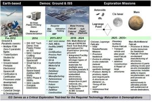
Source: Image courtesy of NASA/John Vickers
Cooper and Griffin of NASA MSFC published a report that referred to direct manufacturing and stated that in remote locations such as the Moon, Mars, or other planets; direct fabrication (manufacturing) could be used to produce items on location (NRC 2000). The report explained how additive manufacturing in microgravity demonstrated the benefits of fused deposition modeling (FDM) to rapidly produce replacement components or repair broken hardware on the Space Shuttle (SS) or the International Space Station (ISS).
Cooper and Griffin conducted low-gravity aircraft experiments to demonstrate the capability of FDM to fabricate in a microgravity environment. Cooper and Griffin developed a hardware implementation plan using FDM for further experiments aboard the ISS. They proposed using an ISS FDM device with a 10 cm × 10 cm × 10 cm volume, mass ~ 45-65 kg, physical envelope of 0.45 m × 0.5 m × 0.6 m using peak power of 300 W with an air cooling of 150 W (Cooper and Griffin 2003). Additive manufacturing holds the potential to extend traditional manufacturing capabilities (Korkut and Yavuz 2022).
Figure 15-2 Microgravity Environments Reduces Thermal and Solute Convection Flows

Source: Image Courtesy of NASA (Volz 2014); (Volz 2014, Nichols et alia 2022).
Manufacturing in space allows the construction of structures and subsystems fully optimized to operate in the zero-gravity environment with impressive volume-to-mass efficiencies (Prater et al., 2018, 2019).
Figure 15-3: Microgravity Environments Minimizes Sedimentation and Buoyancy of Phases

Source: (Volz 2014, Nichols et alia 2022). Image Courtesy of NASA (Volz 2014).
Figure 15-4 ISS Materials Science Facilities: Materials Science Glovebox (MSG) Facilities

Source:(Volz 2014, Nichols et alia 2022). Image Courtesy of NASA (Volz 2014).
The percentage of hardware failures on the International Space Station (ISS) involves polymeric and composite materials (~ 35 %) and are using additive manufacturing techniques on board the ISS. NASA has developed several ways to achieve this including contracts with ‘Made In Space, Inc.’ (www.madeinspace.us) to provide extrusion-based additive manufacturing in microgravity environments on board the ISS (Weinzierl and Sarang 2021). Once printed, an optical scanner is used to verify the integrity of parts made with a view to create procedures to use metals and combinations of materials (Prater et al., 2019).
The ISS 3-D printer made its first 3-D printed object in space in 2014. Figure 15-5 shows the printer during flight certification and acceptance at NASA’s Marshall Space Flight Center, Huntsville, Alabama, prior to its launch to ISS aboard the SpaceX commercial resupply mission. The first objects built in space returned to Earth in 2015 for detailed analysis and comparison to the identical ground control samples made on the flight printer prior to launch. The goal of this analysis was to verify that the 3-D printing process works in the microgravity environment as it does on Earth (Prater et al., 2018, 2019). The printer works by extruding heated plastic, which then builds layer-upon-layer to create three-dimensional products. Long-term space missions would enable on-board manufacturing capabilities to supply needed parts.
Figure 15-5: International Space Station’s FDM Printer

Source: Image Credit: NASA/Emmett Given.
In addition to additive manufacturing, other forms of manufacturing such as free melting of metals (Figure 15-6), mixing of liquids for pharmaceuticals and processing of two-phase solutions are required. Additive manufacturing in space presents new opportunities for recycling. Recycled material has a significant impact on ISS operations. The disposal of waste on the ISS is achieved by detaching from the ISS and burning in the upper atmosphere of Earth. However, using recycled materials will eliminate waste and component/system creation of recycled materials allows feedstock to be produced (Prater et al., 2018).
Figure 15-6: ISS Materials Science Facilities: Low Gradient Furnace (LGF) & Solidification Quench Furnace (SQF)
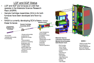
Source: (Volz 2014, Nichols et alia 2022). Image Courtesy of NASA (Volz 2014).
Microgravity environments enable accurate measurements of material properties such as viscosity and surface tension, facilitate nucleation studies, increase the size of crystals that can be grown, and reduces defect densities from contact with container walls (Figure 15-7). Manufacturing hardware enables the production of low-mass systems, thereby reducing launch and storage space. Antennas, booms, and panels are designed for launching and their size and shape are limited in addition to functionality and scale. Manufacturing in space enables the deployment of systems without constraints. Such systems include mirrors, gossamers, antennas, arrays, reflectors, and trusses (Kovalchuk et al. 2022).
Figure 15-7: Microgravity Allows Processing without Containment to Manufacture Items on the ISS
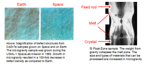
Source: (Volz 2014, Nichols et alia 2022). Images Courtesy of NASA (Volz 2014)
ADDITIVE MANUFACTURING FOR SPACE MISSIONS
There are wide ranges of process options for the user wishing to implement circular manufacturing technologies for space missions. Additive manufacturing (AM) technologies such as stereolithography (SLA), selective laser sintering, fused deposition modeling, ballistic particle manufacture, laser net shaping, etc., are available for use in the space environment. Most of these technologies have evolved from expensive systems producing basic models to relatively low-cost machines producing various components in metals, plastics, wax, and paper for applications such as design aids, rapid tools, and functional prototypes. For those involved in the study of AM, growth of this technology has far exceeded the adoption rate of other laser-based technologies such as welding. In terms of circular economic principles of recycling and reuse, this section examines the most common AM technologies and explores their limitations and advantages for use in space.
STEREOLITHOGRAPHY (SLA)
In the stereolithography process, photopolymers are composed of Photoinitiators and liquid monomers. The sequence of the photopolymerization process is shown in Figure 15-8. Photoinitiators are held in a solution composed of liquid monomers. On exposure to an ultra-violet photon, photoinitiators are excited and a small percentage of these molecules chemically transform to become reactive species. The reactive species stimulates photo polymerization through the formation of a free radical polymer initiation sequence. Additional monomers proceed to react with the chain until the process terminates.
Figure 15-8: Photo-Polymer Reaction Sequence

Source:(Jackson 2023).
Commercial photopolymer AM machines work either by laser-based photocuring or masked-lamp curing. Stereolithography starts with a solid or surface CAD model of a three-dimensional object. A computer program slices the CAD model into many thin layers. The solid model is built in a vat of liquid resin that has the property of changing from liquid to solid when exposed to ultraviolet light. An ultraviolet HeCd laser, U.V. enhanced Ar+, or a frequency quadrupled Nd:YAG laser scans through a series of discrete vectors. At each point, the resin is cured to form a layer (Figure 15-9).
Figure 15-9: Sequential formation of solids through UV laser curing

Source: Author
The overlapping of solids forms a line, and overlapping lines form a solid layer. The depth of cure is a function of laser power and dwell time; a substantial over-cure is produced to ensure layer-to-layer bonding. Figure 15-10 shows layer-by-layer bonding and a cross-section of a cured line.
Figure 15-10: Layer-to-layer Bonding and a Scanning Electron Micrograph Showing the Cross Section of a Cured Line
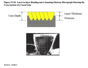
Source: Author
Building a solid object starts by drawing the bottom layer of the object on the surface of the liquid resin (Figure 15-11).
Figure 15-11: Schematic of the Stereolithography Process
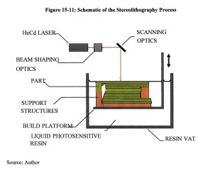
Source: Author
CAD data representing a layer moves the ultraviolet beam across the surface of the liquid resin by controlling the deflection of mirrors. After the entire bottom layer has been exposed and solidified, the layer of solid resin is lowered so that a thin layer of liquid covers the solid layer. Then the second layer of the solid object is drawn on top of the first. As the second layer is drawn, the liquid resin solidifies and adheres to the first layer. This process continues layer-by-layer, until the entire object is complete. The time taken for the process depends on the size and complexity of the object. After the object is completed, it is raised above the resin to allow excess liquid resin to drain. Finally, the object is exposed to a flood of ultraviolet light to complete solidification of the resin. After completion, various finishing processes may be used, depending on the use of the model. There are now many photo-polymer resins on offer ranging from epoxy, vinyl ether, or acrylate functional groups. Each photo-polymer resin will have offer specific build rates and produce models with a range of properties and accuracy.
The speed of a photopolymer is directly associated with the laser exposure necessary to achieve a prescribed cure depth, Cd. Most SLA users wish to know how long it will take to make a build with a particular resin. Information such as resin photo speed will allow the user to make accurate calculations about curing rates for a particular laser power. The resin is exposed to a laser beam scanned at a series of known velocities. The cure depth Cd is then measured and plotted as a function of the incident energy density. The gradient provides the energy requirements of curing per unit volume, Dp, and Ec, is the critical exposure of the resin.
HeCd lasers produced radiant energy in both visible and ultra-violet wavelengths. The UV output provides sufficient energy for curing most photopolymers. Metastable states of neutral Helium atoms are excited. These collide with neutral cadmium atoms, the upper state of the cadmium ion is excited thereby emitting radiation with wavelengths 441.6 nm and 325 nm, which are visible light and ultra-violet light, respectively.
To calculate parameters that will illuminate the SLA AM process, the interaction of light with resin needs to be understood. Radiation that has been transmitted to the surface is absorbed according to Beer-Lambert’s law, I = Io.e-λZ, where the absorption coefficient is determined by the intensity and wavelength of the radiation and the surface medium with which it is interacting. Let us assume that a laser beam is scanned in a straight line with constant velocity. Where the x-y plane relates to the surface of a liquid and the z-axis relates to the penetration through the liquid. Irradiance at any point within the resin can be calculated as a factor of the irradiance incident on the surface of the resin, H (x, y, 0). For an ideal Gaussian laser beam:

Wo relates to 1/e2 Gaussian half-width, which is ~ 13.5% of peak H. When considering that irradiance, H, is termed the ‘radiant power per unit area,’ it can be seen that exposure, E, is a function and as it is termed, ‘energy per unit area,’ which is the integral of irradiance with respect to time. Thus,

Where, E (y, z) = exposure (Jm-2), PL = laser power (W), Vs = laser velocity (ms-1), Dp = penetration depth (m), and Wo = 1/e2 Gaussian half-width (m).
In the case of laser interaction with photopolymers there is a critical value of exposure, Ec. Any value below this and the polymer will remain liquid, any value above this and the polymer will solidify. The transition point between the two states is termed as the gel point where the polymer changes viscosity. It follows that as the laser energy penetrates the resin at some point there will only be enough energy to raise the resin to the ‘gel point,’ i.e., energy absorption by the resin, and at this distance there will be a solidification boundary.
In order that the shape of a curing line is determined, Eq. 15-2 can be used with values set at the gel point. The result is a parabolic cylinder. This effectively produces a single cured line in the direction of travel. The maximum exposure will be at y = 0, so the maximum depth of the curing process can be determined. This is done by first determining what the maximum exposure is at the centre of the incident beam,

The maximum cure depth Cd can now be determined at Zmax:

Cd represents a fundamental side of SLA and provides essential information that can be used to control the laser and determine what effects occur within the resin. As the parabolic cure pattern was determined, the maximum cured line width can also be determined because it will occur on the surface, i.e., z=0. The cured line width, Lw:

This is another important result, namely that the cured line width is directly proportional to the laser spot diameter. When cure depth is increased the cured line width increases by the square root of the cured depth:

Substituting for Emax and solving for Vs:

Laser scan velocity is inversely proportional to laser spot size and decreases exponentially with an increase in the ratio of cure depth/penetration depth (Cd/Dp), i.e., increased cure depths draw more slowly than shallow cure depths. Accuracy is heavily dependent on the thickness of the layers that are used to construct the model. The layer thickness is a user definable parameter and as such can affect build quality. Layers will also affect the quality of the curved surfaces and leads to a phenomenon called stair stepping. Stair stepping affects build time, accuracy, and cost. Stair stepping phenomena affect all AM processes. Part orientation can reduce stair stepping effects and is essential to maximize part accuracy. Here are some common guidelines: define the most important surfaces, orientate part for best build, use adaptive slicing procedures for maximum resolution and position surface with respect to steps for ease of finishing. Support structures are necessary to maintain part integrity while it is being constructed: (1) supporting ‘island’ structures – it is extremely important that each layer has a layer of some form underneath to attach itself to. With complex geometry this is often not the case and supports are therefore needed to ensure the cured resin does not float away; (2) support to reduce part distortion where solidification takes place there is likely to be an amount of distortion. This can be constrained by placing support structures that maintain tension during contraction. The result is stress concentrations, but the part will be geometrically superior.
In order that SLA parts to be built to the highest degree of accuracy there must be some form of calibration of the mechanisms within the machine. For example, over time the diameter of the beam will change as the cavity ages. Optical alignment may shift due to small temperature variations. Mode structure may alter due to internal misalignments from small vibrations and the laser power reading of the SLA may drift from the calibrated value. Practical studies into this problem have shown interesting results. Studies into accuracy show that the major sources of inaccuracy are shrinkage and laser linewidth, both of which can be compensated for by the equipment user and the hatch pattern.
The limiting factor that controls the speed of the SLA process is the re-coating time. Free liquid surfaces are very problematic, they must be given settling time after a disturbance such as dipping. Meniscus effects will distort the liquid level around surface features of the model. Hence, a doctor blade is used to level the resin after each layer and before each slice exposure is commenced. The problems are compounded by fluid dynamics of the sweeping motion. The blade is competing with surface tension forces acting on both the blade and part within the vat. There are additional affects which produce a build-up of resin ahead the of the blade which then provides a pressure gradient that drives resin underneath the blade as it sweeps across and affects the thickness of the resin coating behind the blade. The effects are a function of the resin temperature, viscosity, doctor blade geometry and velocity (Figure 15-12).
Figure 15-13 shows the workings of the Zephyr re-coating system that is now provided for most 3D SLA systems as an upgrade option. The blade deposits a curtain of resin directly onto the new surface thereby minimizing the time for re-coating and the effects of dragging and displacing the resin through sweeping.
Figure 15-12: Factors Affecting the Sweeping Process
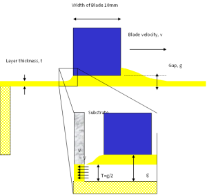
Source: Author
Figure 15-13: The Zephyr Re-coating System
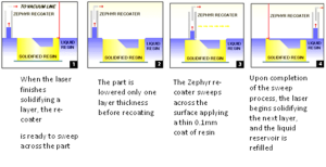
Source: Author
In order to prepare the new layer for curing, issues must be addressed: the resin surface must be maintained at the focal plane of the imaging system; the surface must be uniformly flat, level, and free of extraneous features; the surface must be a controlled distance above the previous layer; and control systems are essential!
The resin surface position must be known. Light-bounce techniques are employed to locate surface, Diode Laser Levelling System (DLL). Layer thickness is usually around of 100-200 sq. m. Surface positioning typically requires positional control of 3-7% of the layer thickness, about 7.5mm. Location can be determined allowing feedback to the liquid control system and speeds are increased (Figure 15-14). Laser spot size influences the irradiance (energy distribution), which in turn will affect depth of cure, width of the cured line, and the extent of overcure. We must therefore keep the illumination conditions constant across the whole area of the vat. An alternative is a flat-field focusing lens that maintains the focal properties across the vat and forces the beam to interact with the resin at near normal incidence (Figure 15-15). This system is commonly used in laser marking systems. The way in which the object is cured within its layer boundary determines the level of internal stress and shrinkage factors. Part accuracy can be improved by careful choice of hatch pattern as there are many to choose from. Hatch patterns determine part accuracy, hatching is used to photo cure the liquid in the interior regions of the part. Hatch pattern determines the amount of curing within an object which therefore affects its physical properties and internal stresses and many patterns have been developed Tri-hatch uses a scanned line parallel to the x-axis combined with lines at 60 and 120 degrees to the x-axis.
Figure 15-14: Level Determination on the Resin Surface
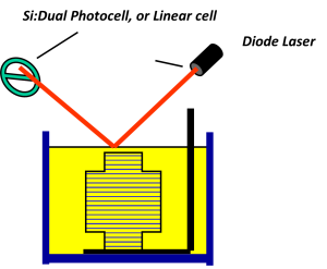
Source: Author
Figure 15-15: Using a Flat-field Lens to Correct for Focal Displacement

Source: Author
There is approximately 50% uncured resin within the triangular matrix, which is cured in post processing generating high distortion. The Weave adopts two orthogonal vector sweeps per layer. The amount of uncured resin is reduced, part accuracy is increased along with build speed. Errors on the corners are often observed. STAR-Weave is a staggered hatch pattern, alternative sequencing, and retracted hatch offsets every other layer of the x- and y-hatch vectors. It prevents x-and y-hatch overlay and reduces stress build up. A retracted hatch keeps endpoints from bonding with the border.
The following advantages are associated with SLA:
- It can use several types of resin with varying properties apart from the resins from Ciba-Geigy.
- It has good surface finish and accuracy.
- It has a good speed depending on model types.
- The SLA does not require any attendant when it is in operation, it can be left to run on its own.
- Parts can have both internal and external contours and shapes.
- The SLA can build multiple parts at once.
- The SLA can be used to produce complex geometry. SLA produced parts can be used to create patterns for soft tooling, with part design duplicated in a polyurethane material that more closely approximated the acrylonitrile butadiene styrene (ABS) material from which the actual part would later be made. It can also be used for mold making for casting operation.
- Parts produced by SLA are used for flow test visualization; and
- Parts produced by SLA are used as investment casting patterns.
Despite all the accompanying advantages, the SLA has some disadvantages:
- Shrinkage and distortions are present in the material. This leads to layers separating from the structure.
- The surface finish depends on the slice thickness and material. Also, the accuracy greatly depends on the parts complexity.
- It needs a lot of finishing operations that can be tedious and messy. This will lead to the purchase of finishing apparatus that is an added cost. Post cure is required for all the resin-based processes either acrylic or epoxy resin.
- Large and thin flat structures are most difficult to produce and hold within tolerance. The Engineers compensate for these effects by altering the part’s orientation or by adding the proper type of fixing to hold the features in position during the post-curing process, a lot of the stresses that cause the part to wrap are basically molded in, so when the supports are removed, there is a good chance that the wall is going to warp.
- Surface finish and tolerance are not complementary. Orienting a part one way may result in higher accuracy and a less attractive surface finish. Conversely, orienting the part another way may lead to a smoother finish with less precise tolerances.
- The use of expendable patterns generated with the aid of SLA is not without problems. Because of the high thermal expansion characteristics of the polymers used in SLA, use of patterns created with the process can result in mold cracking or breaking during burn-out.
- For each part, a support structure must be modeled and designed in the CAD system; and
- Unlike other systems, Process does not produce very fine tolerances. Hence tolerance of ±0.0013 mm is not possible for now with SLA, which is ±0.2 mm in x-y plane.
A clear advantage of using SLA in space is its ability to convert liquids into solids and the solids to be used for feedstocks/fillers for other AM processes such as FDM. The use of lasers to fuse materials can be extended to metals making selective laser sintering (SLS) a technique that will be of great use in the space environment especially for the creation of very high strength alloys and alloys that cannot be manufactured on Earth.
FUSED DEPOSITION MODELING
Fused Deposition Modeling (FDM) processes uses thermoplastic wire-like filaments that are melted in the deposition head. The material is then extruded from the head and deposited on a layer-by-layer basis. The layering lamination technique is based upon the rapid solidification (~ 1/10 second) of the molten laminate material from the Modeling filament. The semi-liquid thermoplastic material is deposited onto thin layers, building the model upwards off a fixture base. The plastic or wax material solidifies in place positioned by the x-y controlled extrusion head. A precision volumetric pump is used to control the material passing through the extrusion orifice. The extrusion process shears the material, and it quickly solidifies while bonding to the previous layer by heating it and then fusing. The model is fabricated upon a piston, which is lowered between layers to make room for the next layer. This process is repeated until the part is fully built.
A series of cassettes or spools supplies the system with a polyester compound. Each cassette holds 50 rectangular wafers. A stapling mechanism feeds the wafers into a pressurized heated channel that supplies the material to a viscosity pump. To ensure accuracy, the material is extruded through a 150-300 mm diameter orifice at a controlled rate. Parts are built on a thermally controlled metallic substrate that rests on a table. As each layer is extruded, it bonds to the previous layer and solidifies. The pump head, table and gantry move in the x, y, and z axes, respectively.
Supports for the parts are built from the same polyester material, using a support-generation algorithm. The system creates perforations where supports adjoin the model, making it easy to snap off any required supports. Printed models often require fewer supports than other systems’ models due to precise pump control. A technique called “bridging” allows the material to be extruded across a distance without supports. Thin perimeter walls are created, and the pump head fills in the area, creating a flat surface between the walls. This technique speeds build time and maintains a good surface finish. No special clean-up is required.
Modeling filaments include ABS, medical grade ABS, (ABS prototypes have 85% of the strength of an actual molded part), investment casting wax, thermoplastic elastomers, and many other materials. Models can be marked, sanded, painted, or drilled. Accuracy of the models can be produced within ±0.127 mm (±.005 in). Layer Width / Thickness: Operator may optionally select road widths between 0.254 to 2.54 mm (0.010 to 0.100 in) and thickness from 0.05 to 0.762 mm (0.002 to 0.030 in). The advantages of FDM include:
- All the materials that are used for this process are non-toxic, hence it is safe for office use.
- It is a high-speed process. Layers are laid at speeds up to 23 m/min.
- The parts do not require support structure while building. There is no material wastage or cleaning. However, 3D Modeler creates a support in mid-air rather than building the support up from the base as in other applications.
- It is excellent for making investment-casting pattern using wax. Parts produced by FDM processes emerge fully cured so that they can be used immediately or can be treated after grinding, painting, etc.
- It uses varieties of heat-fusible thermoplastic filament materials and wax filaments. For example, machinable wax, ABS like plastics, investment casting wax and nylon.
- The system is also capable of extruding plastic into free space depending on the part geometry; and
- It is a desktop system that can operate in an office environment without any special ancillary service.
The disadvantages include:
- The following disadvantages are peculiar to the FDM process.
- Part strength is limited to adhesion/fusion between filaments.
- It requires support structure for some parts.
- There is the problem of delaminating of parts due to poor bonding between layers; and
- The operating temperature of between 82 and 105 oC makes it suitable for office use and puts a natural limit on the useful in-service temperature range of parts.
The method of manufacturing objects as a series of horizontal layers poses a unique set of problems, irrespective of the techniques involved in the fabrication of each layer. This section is intended to provide the reader with some insight into the considerations that must be made when building parts by layered manufacturing techniques.
STAIR-STEPPING PHENOMENON
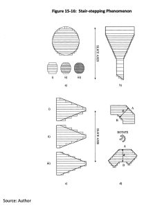
The slicing process described earlier produces a set of horizontal cross sections, each of these sections conforms to the geometry of the original CAD model to a degree of accuracy, which is significant to the entire process. However, each layer is of continuous cross section through its thickness (i.e., in the Z-direction), and therefore parts cannot accurately conform to the CAD geometry in the vertical plane. This is best illustrated by considering the situation shown in Figure 15-16. A cylinder has been built with its circular cross section parallel to the slice axis, i.e., perpendicular to the layers. If any single part layer is considered, slicing software has produced a layer, the top surface of which conforms precisely to the CAD geometry. However, because the layer is rectangular in cross section it cannot conform to the curved surface across its entire thickness, the largest deviation at its bottom surface. This results in the stepped effect shown which has been termed the stair-stepping phenomenon.
Figure 15-16: Stair-stepping Phenomenon
Source: Author
Layer Thickness
It is clear from the example shown in Figure 15-16 (a) that the smaller the slice thickness, the greater the resolution of the final part (as shown by cylinders (i) to (iii)). It may seem sensible to use the smallest possible layer thickness that can be physically created by the system, but the smaller the layer thickness, the more slices are required resulting in longer data processing time, larger data files and a longer build time. To optimize the process, variable layer thickness may be used over different ranges of the part. The example of the funnel shown in Figure 15-16 (b) has a fine layer thickness where the surfaces are sloped, and stair-stepping is more pronounced, and thicker layers on the vertically sided sections.
Effects of CAD Geometry
In the two examples provided so far it is the top surface of each layer that conforms to the CAD geometry, and this is the case in many of the commercially available systems. The reason for this can be seen if we consider the SLA process in which a laser beam is guided across the surface of a vat of liquid polymer, tracing out the geometry of each layer, and whenever the laser strikes the resin surface, a small volume is cured and solidified to a depth dependent on laser power and scan speed. The top surface of the layer must conform to the CAD geometry because that is what is drawn on the resin surface, with a continuous depth cured below it provides the layer thickness.
Figure 15-16 (c) shows three different ways in which the layers might conform to the CAD geometry, in each case the shaded areas represent the deviation from the true geometry. Example (i) shows the case where the top of each section conforms to the required layer outline, and example (ii) shows the opposite case in which layers are formed from the bottom up. It is clear from these examples that extent of deviation will be dependent of the gradient of the sloping surface, and whether the error is positive or negative will depend on the direction of slope. In many cases the most favorable situation would be where all deviation was positive and excess material could then be carefully removed to leave the accurate part. However, the additional processing power required to produce the necessary data corrections ensures that only positive deviations may prove prohibitive over the layers. The situation shown in example (iii) represents the intermediate case where the center of each layer conforms to the CAD geometry, resulting in smaller deviation in both directions. This would produce the most accurate parts in terms of maximum deviation, but again a large amount of additional processing power would be required.
Part Orientation
The manual finishing of parts built by layered manufacturing to remove the stair-stepping effect is the most labor-intensive phase of the process, and great skill is required if dimensional accuracy is to be maintained. The only part surfaces that will not exhibit stepping are those built parallel to the slice plane, and therefore parts should be oriented so that cosmetically important faces are built in this direction and important dimensions are built parallel to the slice axis. Figure 15-16 (d) shows how a simple 45O rotation improves the surface finish of faces A and B, and maintains the accuracy of dimension. However, this may have a detrimental effect on other features of the part and so a suitable balance must be found. This analysis assumes that the ‘as built’ geometry is more accurate than the hand finished geometry, but this depends on the skill of the model maker and the accuracy of the process.
The build time involved in the fabrication of any part is principally dependent on the number of layers involved, and may therefore be minimized through careful selection of the part orientation. However, it is not simply a matter of choosing the orientation with the smaller z-height because all the other effects discussed must also be considered, and a compromise must be made. In many layered manufacturing systems, the degree of part distortion occurring as a result of the layer generation process is department on the orientation of the part with respect to the slice axis. Therefore, another consideration is introduced in selecting the most suitable build orientation.
SUPPORT STRUCTURES
In any manufacturing technique the workpiece must be mounted or supported in some way in preparation for processing, for example held in the vice of a machine tool or the chuck of a lathe. AM processes also require to be mounted to hold it in position, and further structures are often required to support unstable geometry as they are built. The principal benefits achieved by these systems stem from the fact that the processes are fully automated, and that part specific fixtures or tooling are not required, and therefore it is not possible to manually position prefabricated fixtures and still reap the same benefits. However, the fact that rapid prototyping systems fabricate whatever is described by the CAD input means that they can build any support structures in the way that they build the parts, thereby maintaining their flexibility and automated nature.
Initially, support structures were designed on the CAD systems in conjunction with the part, but this was labor intensive, and the operator was required to have a full understanding of the part building process. Software packages have been developed which generate the design of any required supports automatically by inspecting the part geometry and assessing what is required. The support designs are then sliced in the way as the part and incorporated into the build information sent to the fabricator. The supports are fabricated in the same way as the part and are incorporated into it, but are normally in the form of grids of very thin webs that may easily be removed once the part is complete.
Support structures perform the following important functions:
Act as a mounting device holding the part in position as it is built.
This is particularly important in those techniques that form parts from a vat of liquid resin (e.g., stereolithography) where the bottom layer must be firmly attached to the build platform to stop the part floating away.
Act as a constraint reducing part distortion
In many rapid prototyping processes, the procedures involved in creating individual layers from their raw materials involves either a total phase change (e.g., liquid resin cured to solid resin) or localized heating and cooling cycles (e.g., selective sintering of powdered materials). In either case the degree of material shrinkage causes some part distortion. Supports may be used to constrain these distortions to some extent thereby improving part accuracy. Part distortion can also occur due to faulty STL files. Missing points, missing facets or just poor data manipulation algorithms may cause distortion in the final object. However, with the right procedures in place, the problems associated with the building process can be minimized.
SPACE STRUCTURES AND SPACE COMPLEXES
The exploration of space for manufacturing purposes is enabled by systems and complexes that provide physical infrastructure, technologies, and operations required for space exploration. The complexes play a crucial role in enabling manufacturing processes and systems to operate beyond the confines of Earth to manufacture products in space using the advantages provided by an environment that promulgates innovations in products and processes.
Space systems refers to hardware, software, and communications designed to operate in the space environment. Space systems are needed for scientific research, satellite deployments, interplanetary missions, and space exploration. Satellites form a fundamental part of space systems and monitor weather, communications, etc., (Figure 15-17). Orbiting spacecraft provide data for weather forecasting, communications, and monitoring the Earth environment. Advanced propulsion systems, navigation, and communication protocols are integrated into space systems to ensure the successful and efficient process of manufacturing in space.
Figure 15-17: NASA’s Earth Science Satellite Fleet

Source: Image Courtesy of NASA, July 12, 2023. (https://earthobservatory.nasa.gov/images/81559/nasas-earth-science-satellite-fleet).
Space complexes, known as spaceports or launch facilities, serve as the gateways to space and the manufacturing environment. These facilities include launch pads, control centers, and assembly buildings. They provide the infrastructure and resources to prepare, test, and launch spacecraft. Space complexes, such as Kennedy Space Center in Florida (Figure 15-18), Baikonur Cosmodrome in Kazakhstan, and the European Spaceport in French Guiana, are space complexes that coalesce scientists, engineers, and technicians from different countries to work towards refining the processes associated with space manufacturing. Space complexes are not only vital for government space agencies such as NASA, Roscosmos and ESA, but also for private space companies like SpaceX, Blue Origin, and Virgin Galactic, companies that are pioneering space travel that creates opportunities to manufacture in space products that cannot be made on Earth such as immiscible alloys, high purity pharmaceuticals and defect free semiconductors.
Figure 15-18: Kennedy Space Center’s Vehicle Assembly Building on April 29, 2021

Source: Credits: NASA/Frank Michaux.
The preparation of materials on Earth using simulated conditions of space have been developed based on weightlessness and numerical models of material behavior using facilities on Earth. Ground facilities include drop towers, buoyancy pools, air-borne laboratories, and balloons. Space complexes on Earth includes short span microgravity experiments up to 10 minutes, but the real measure of the ability to manufacture in space is due to experiments conducted on space complexes.
The International Space Station (ISS) is a space complex (Figure 15-19) that serves as a manufacturing laboratory. Here, highly specialized materials have been created for the purpose of manufacturing products and secondary work has been done to understand the conditions of manufacturing in space, i.e., heat and mass transfers and solidification processes that involve the formation of dendrites and grains.
Space systems and space complexes are set to increase the significance of the development of manufacturing processes that take advantage of zero gravity conditions in a vacuum with the elimination of convection currents. Exploration projects, such as NASA’s Artemis, aim to return to the Moon to prepare for missions to Mars. This will require the development of advanced launch systems, habitats, manufacturing processes and systems and life support systems.
Figure 15-19: The International Space Station

Source: Image courtesy of NASA, July 13, 2023 (https://www.nasa.gov/press-release/nasa-administrator-statement-on-russian-asat-test).
The emergence of private companies such as Space Forge has added a new dimension to space manufacturing. With the advent of reusable rockets and satellites, space complexes are witnessing a surge in activity that is driving innovation, making space more accessible, and pushing the boundaries of what is possible in space manufacturing (Weinzierl and Acocella, 2016). The conditions required to produce high performance materials include understanding gaseous and liquid phase processing of feedstocks, converting to a liquid phase followed by solidification and casting. These are energy intensive processes and so the space complex must be designed to provide the required energy needed to manufacture products in space. Early studies of manufacturing in space relied on space complexes operating in a weightless environment, with a limited size and power limitations. Therefore, the design of space systems and complexes specifically for manufacturing need to be developed to advance space exploration where items are made rather than taken from Earth.
ECONOMY-ORIENTED SPACE MISSIONS AND STRATEGIES
Economy-oriented space missions and strategies refer to initiatives and approaches that focus on using space resources and activities to stimulate economic growth and development. Economy-oriented space missions and strategies include:
Space Manufacturing: Using the conditions of space, such as microgravity and vacuum, so that private enterprises can manufacture products that cannot be made on Earth, such as pharmaceuticals, materials, advanced semiconductors, and the production of advanced nanotechnologies. Commercializing these activities can lead to economic benefits and technological advancements (Weinzierl and Sarang 2021, Weinzierl et alia 2021).
Resource Extraction: There are various resources in space that can be mined, including rare metals, water, and oxygen. Developing technologies and strategies for extracting and using these resources will lead to a new space-based economy (Weinzierl and Acocella 2017, Weinzierl and Haddaji, 2019, Weinzierl et alia 2021).
Space-based Energy: Capturing solar energy in space using large-scale solar arrays, suing it for manufacturing purposes in space or transmitting it back to Earth wirelessly is a goal that is highly desirable. Space-based energy systems could provide a virtually unlimited and clean energy source, revolutionizing the energy sector and creating new economic opportunities for manufacturing industries.
Space Debris Cleanup: As space debris poses a growing threat to satellites and space missions, there is a need for technologies and missions aimed at removing or mitigating debris. Developing cost-effective cleanup strategies could not only improve space operations but also create a feedstock for circular manufacturing systems in space (Weinzierl et alia 2016).
Space Tourism and related development of consumer goods: The rise of space tourism presents significant commercial opportunities. It could create demand for consumer goods and products specifically designed for the space environment. This could range from clothing and food to entertainment and personal care products. Manufacturing these goods in space could cater to the emerging space tourism market and create new economic opportunities. Further, space manufacturing can contribute to the development of space tourism infrastructure, including the production of spacecraft, habitats, and life support systems specifically designed for space tourists (https://hbr.org/2021/02/the-commercial-space-age-is-here).
These are just a few examples of economy-oriented space missions and strategies. As technologies advances and space exploration continues, new opportunities will emerge, enabling the development of a strong space economy.
ECONOMIC FEASIBILITY OF SPACE-RELATED ACTIVITIES AND MISSIONS
Economic feasibility largely depends on technological and infrastructure readiness, regulatory framework, and market dynamics.
Technological and infrastructure readiness is a required condition for commercialization of space which includes activities such as low-cost, frequent launch capabilities; in-space manufacturing; scalable habitats; in-space resource extraction and energy collection; and reliable radiation shielding and debris mitigation. This is evidenced related to space transportation with the public-private partnership called Commercial Orbital Transportation Services (COTS) developed by NASA in 2005. COTS allowed NASA to adopt a more targeted role focused on space exploration and basic science, leaving economic development of space largely to the private sector. It also made NASA a customer and partner of its private contractors. Thus, this public-private partnership approach allowed for a self-reinforcing virtuous cycle of development that could support the space economy. As an example, Weinzierl (2018) explains cheaper and more frequent rocket launches might facilitate short-term tourism, along with industrial and scientific experimentation on suborbital and orbiting spacecraft. Routine activities could lead to demand for commercial habitats and longer flights, leading to increased demand for resources in space and opportunities for complementary activities.
Space missions are often funded by governments through space agencies like NASA (United States), ESA (European Space Agency), Roscosmos (Russia), and others. These agencies allocate budgets for research, development, and space exploration. Government funding is driven by various factors, including national interests, scientific objectives, defense considerations, and international collaborations. Regulatory framework could encompass multiple dimensions, from property rights considerations to distributional concerns, and mitigating negative externalities that can arise due to space-related activities. The space debris problem hints at the tragedy of commons scenario and threatens to become unmanageable if regulatory oversights are not exercised. It is a classic example of negative externalities, and conventional remedies suggested by economic theory such as standard Pigouvian price on debris fails in this case since there is no established space taxing authority (Hansen 2016). Lack of delineated property rights additionally make it harder to quantify and internalize externalities related to space debris. With respect to regulatory purview, a concerted effort to enact international treaties and agreements would be instrumental in resolving many potential challenges associated with space activities currently and in the future. Some policy questions that need to be considered when developing a commercial space sector in a country include government’s role in coordinating and subsidizing interdependent technologies, nature of subsidies to implement such as cost-sharing, revenue guarantees, incentives etc. (Weinzierl 2018).
Market dynamics considerations play out when a centralized model is transformed to a decentralized one. Typically, public goods provisions are guaranteed in a centralized model and typically left underprovided if left to the market. High demand and cost conditions in a sector can be instrumental in paving the way for a decentralized model. For example, the COTS program allowed NASA to leverage private capital to acquire required services cheaply. Apart from subsidizing commercial launch vehicles, a competitive market structure was developed due to a diversified set of award contracts. Additionally, decentralization also spurred activities and innovations, broadening the space economy. Market structures and functioning depend on analyzing demand conditions and associated costs:
- a) Market demand and revenue generation opportunities for space-manufactured products need an assessment of the market potential, competitive landscape, pricing strategies, and potential partnerships or customers. Some factors beyond the conventional needs such as space manufacturing, resource extraction etc. that can stimulate demand for space activities are potential for spin-off technologies that have applications beyond space exploration. Many everyday technologies and innovations have been derived from space-related research and development, including satellite communication, miniaturized electronics, improved materials, and medical advancements. These spin-off technologies can have significant economic impacts across various industries. New markets and industries can also develop which could include space-based construction, manufacturing facilities in space, space-based agriculture, and manufacturing goods specifically tailored for space habitats or off-world settlements. These new markets can foster economic growth and provide novel business opportunities.
- b) Various factors that need to be considered when analyzing costs towards space activities such as in-space manufacturing and space missions include:
- Cost of Development: The development and construction of space missions includes costs associated with research and development, design, engineering, manufacturing, and testing spacecraft, launch vehicles, ground infrastructure, and other necessary equipment.
- Launch Costs: Some of the expenses could include launching manufacturing equipment, raw materials, and supplies from Earth to space, payloads into space using rockets or other launch vehicles. The development of reusable rockets and in-space refueling infrastructure could potentially reduce these launch costs.
- Operations and Maintenance Costs: Space missions would include costs associated with tracking and communication systems, data analysis, mission control operations, ground support, and maintaining the health and functionality of the spacecraft. In-space manufacturing costs would include the costs of personnel, power supply, monitoring and control systems, waste management, and regular maintenance and repairs of the manufacturing equipment and facilities.
- Resource Acquisition Costs: In-space manufacturing often relies on utilizing local resources, such as asteroid mining or lunar resource extraction. Evaluating the expenses associated with identifying, extracting, and processing these resources, development of resource prospecting technologies, mining techniques and refining processes would be required.
- Labor Costs: Assessing labor costs is essential when considering human involvement in in-space manufacturing operations and space missions. Costs include training and supporting astronauts or space workers, as well as potential automation and robotic systems that could reduce labor requirements and associated expenses.
- Cost Reduction Strategies: International collaborations and public-private partnerships can help distribute costs and share resources. Launch costs can be reduced by utilizing local resources, avoiding transportation expenses, and minimizing reliance on Earth-based supply chains. Other strategies include reusable rockets, 3D printing of spacecraft components, miniaturization of satellites, and increased automation in manufacturing and operations. Instead of relying on Earth-based supply chains and waiting for resupply missions, astronauts or automated systems could produce and repair parts, tools, or equipment as needed, leading to on-demand manufacturing and repair capabilities. This reduces the need for stockpiling and improves mission sustainability.
- Scale and Efficiency: Economies of scale can be realized when average costs fall by increasing production. The company Space Exploration Technologies (SpaceX) demonstrates both economies of scale and efficiency characterized by reusability, reusability without over-engineering, and vertical integration. Even though reusability imposes new costs such as research and development to establish vertical landing capabilities, operating expenses to recover spacecraft and fairings, and refurbishment efforts between launches; enough demand and low average costs were instrumental for its successes. SpaceX sought to take advantage of a virtuous cycle in which growth led to cost reductions and, thus, more growth through lower prices (Weinzierl et al. 2021). Cost efficiency was realized by focusing on reliability without over-engineering and vertical integration. SpaceX used off-the-shelf components, and previously used, proven technologies wherever possible rather than developing new, custom-built technology. Highly vertically integrated structures allowed them to eliminate transaction costs throughout the supply chain.
CONCLUSIONS
The developments of manufacturing in space are wide and include planetary mining and manufacturing on planet, asteroid mining and manufacturing, and manufacturing in orbit. The challenges to integrate systems to minimize waste and effort are significant. The space environment develops materials that cannot be made on Earth owing to differences in gravity or environmental factors. The scientists of the future will need to design and build systems and complexes to support the economy-oriented approach to manufacturing products in space and the complexities associated with costs associated with this activity need to be fully understood and their effects quantified.
QUESTIONS
- Describe the concept of ‘manufacturing in space’.
- How does the microgravity environments affect the structure of materials and how they are manufactured into parts, components, systems, and sub-systems?
- What are manufacturing standards and how are they harmonized?
- Describe the type of equipment used on the International Space Station (ISS) to study the effects of microgravity on the properties of materials.
- Why is manufacturing in space different to manufacturing on Earth? Compare and contrast the differences.
- Why is the application of systems engineering principles critical to manufacturing in space?
- Describe space missions for manufacturing in space.
- What are the initiatives that make up the economy-orientation space missions?
- Explain how space missions are funded and why they are funded in the first place.
- Why did Blue Origin and SpaceX become so successful in such a short space of time and how did they reduce the costs associated with space travel?
REFERENCES
“Acoustical Signature Analysis for In-Situ Monitoring and Quality Control for In-Space
Manufacturing.” MetroLaser, Inc. Small Business Innovative Research (SBIR) abstract. 2018. < https://www.sbir.gov/sbirsearch/detail/1559789>
AM Sub-Platform, 2013 Additive Manufacturing: Strategic Research Agenda, Version 2, http://www.rm-platform.com/linkdoc/AM_SRA_ FINAL-V2.pdf.
Anderson, Janet. “NASA to Demonstrate Refabricator to Recycle, Reuse, Repeat.” NASA Press Release. 14 November 2018. < https://www.nasa.gov/mission_pages/centers/marshal l/images/refabricator.html>
Bagwell, Roger. “Additive Manufacturing of PEEK and Fiber-Reinforced PEEK for NASA Applications and Custom Medical Devices.” Proceedings of the National Space and Missile Materials Symposium, Henderson, NV. June 2018.
“Automated In-Process Quality Control of Recycled Filament Production and FDM Printers.” Cornerstone Research Group. Small Business Innovative Research (SBIR) abstract. 2018. < https://www.sbir.gov/sbirsearch/detail/1559745>
Bhundiya, H.G., Royer, F. & Cordero, Z. Engineering Framework for Assessing Materials and Processes for In-Space Manufacturing. J. of Materials Eng and Perform, 2022, 31, 6045–6059. https://doi.org/10.1007/s11665-022-06755-y
Bocken, N.M.P., de Pauw, I., Bakker, C., van der Grintern, B., Product design and business model strategies for a circular economy. J. Industr. Prod. Eng., 2016. 33(5): p. 308-320.
Boling, Rich. “3D Printer for Human Tissue Now Available for Research Onboard the ISS National Laboratory.” ISS National Lab. 13 August 2019. < https://www.issnationallab.org/blog/3d-printer-for-human-tissue-now-available-for-research-onboard-the-iss-national-laboratory/>
Brundtland, G.H., 1987. Our common future: Report of the 1987 World Commission on Environment and Development. United Nations, Oslo.
Brussels. Lieder, M., Rashid, A. Towards circular economy implementation: a comprehensive review in context of manufacturing industry, 2016, J. Clean. Prod. 115, 36–51.
“CRISSP Custom Recyclable International Space Station Packaging.” Small Business Innovative Research (SBIR) abstract. 2017. www.sbir.gov/sbirsearch/detail/1148879
Cooper K. and Griffin M., Microgravity Manufacturing Via Fused Deposition, NASA TM-2003-212636 (https://ntrs.nasa.gov/citations/20030067856).
Ellen MacArthur Foundation (EMF), 2013. Towards the Circular Economy, vol.1. Isle of Wight.
Ellen MacArthur Foundation. Barriers policy can be overcome. 2017 (cited 9 August 2022).
European Powder Metallurgy Association, “European Additive Manufacturing Group (EAMG),” http://www.epma.com/european- additive-manufacturing-group, accessed March 11, 2014
European Commission. Closing the loop – An EU action plan for the Circular Economy, Com (2015) 614 communication from the commission to the European parliament, the council, the European economic and social committee, and the committee of the regions.
“Feedback Sensors for Closed Loop In-Space Manufacturing.” Cybernet Systems Corporation. Small Business Innovative Research (SBIR) abstract. 2018. < https://www.sbir.gov/sbirsearch/detail/1559783>
Fischer-Kowalski, M., et al., “Methodology and Indicators of Economy-wide Material Flow Accounting”. 2011. 15(6): p. 855-876.
Geissdoerfer, M. and Savaget, P. and Bocken, N.M.P. and Hultink, E.J. The circular economy – a new sustainability paradigm? Journal of Cleaner Production., 2017, 143. pp. 757-768.
Gradl, P., Tinker, D.C., Park, A. et al. Robust Metal Additive Manufacturing Process Selection and Development for Aerospace Components. J. of Materials Eng and Perform, 2022, 31, 6013–6044. https://doi.org/10.1007/s11665-022-06850-0
Hansen, Ward. 2016. “Pricing Space Debris.” New Space 2 (3): 143-44.
Haskel, J., Westlake, S., 2018. Capitalism without Capital: the Rise of the Intangible Economy. Princeton University Press, Princeton, New Jersey
Hofmann D., Borgonia J., Dillon D., Suh E., Mulder J., and Gardner P., “Applications for Gradient Metal Alloys Fabricated Using Additive Manufacturing,” NASA Technical Brief, Jet Propulsion Laboratory, October 1, 2013, http://www.techbriefs.com/component/ content/article/17446.
https://www.cape.osd.mil/files/OS_Guide_Sept_2020.pdf
https://www.nasa.gov/pdf/140643main_ESAS_12.pdf
https://ntrs.nasa.gov/api/citations/20170009900/downloads/20170009900.pdf
Huebner, Lawrence. “Archinaut Technology Development: Ground-Based Results for External In-Space Additive Manufacturing and Assembly.” Proceedings of the National Space and Missile Materials Symposium, Henderson, NV. June 2018.
“In-Space Manufacturing (ISM) Multi-material Fabrication Laboratory (FabLab).” Broad Agency Announcement. 11 April 2017. www.fbo.gov/index?s=opportunity&mode=form&tab=core&id=8a6ebb526d8bf8fb9c6361cb8b50c1f8&_c view=1
“In Situ Monitoring and Process Control.” Made in Space. Small Business Innovative Research (SBIR) abstract. 2018. < https://www.sbir.gov/sbirsearch/detail/1559743>
“In Situ Monitoring of In-Space Manufacturing by Multi-Parameter Imaging.” LER Technologies. Small Business Innovative Research (SBIR) abstract. 2018. https://www.sbir.gov/sbirsearch/detail/1559833>
Jackson, M. J., Additive Manufacturing Technologies, Kansas State University Course Notes for MET 231 Physical Materials and Metallurgy, Kansas State University, January 2023.
Kim, H. Wu, D.I. Moon, M.L. Seol, B. Kim, D.I. Lee, J.W. Han, and M. Meyyappan. “Carbon nanotube Based Gamma Ray Detector.” ACS Sensors. Volume 4, 2019, pp. 1097-1102.
Korkut, V., Yavuz, H. In-Space Additive Manufacturing Based on Metal Droplet Generation Using Drop-on-Demand Technique. J. of Materials Eng and Perform, 2022, 31, 6101–6111. https://doi.org/10.1007/s11665-022-06865-7
Kovalchuk, D., Melnyk, V. & Melnyk, I. A Coaxial Wire-Feed Additive Manufacturing of Metal Components Using a Profile Electron Beam in Space Application. J. of Materials Eng and Perform, 2022, 31, 6069–6082. https://doi.org/10.1007/s11665-022-06994-z
Kurk, Andy. “Sintered Inductive Metal Printer with Laser Enhancement.” Proceedings of the National Space and Missile Materials Symposium, Palm Springs, CA. June 2017.
Mantel, K., 1990. Wald und Forst in der Geschichte. M. & H. Schaper, Hannover.
Marsh, Doug. “The VULCAN Advanced Hybrid Manufacturing System.” Proceedings of the National Space and Missile Materials Symposium, Henderson, NV. June 2018.
METI, 2004. Handbook on Resource Recycling Legislation and 3R Initiatives. Tokyo: Japanese Ministry of Economy, Trade, and Industry.
Momeni, K., Neshani, S., Uba, C. et al. Engineering the Surface Melt for In-Space Manufacturing of Aluminum Parts. J. of Materials Eng and Perform, 2022, 31, 6092–6100. https://doi.org/10.1007/s11665-022-07054-2
Moraguez, M., O. DeWeck, and T. Prater.“Suitability of Manufacturing Processes for In-Space Manufacturing of Spacecraft Components.” Proceedings of the 70th International Astronautical Congress, Washington, D.C. 2019.
Muhlbauer, Rachel. “Food-safe, skin contact-safe, and medical device 3D printing for manned space missions.” Proceedings of the National Space and Missile Materials Symposium, Palm Springs, CA. June 2017.
Muhlbauer, Rachel. “Metal Advanced Manufacturing Bot Assembly (MAMBA) Process.” Small Business Innovative Research (SBIR) abstract. 2017. http://sbir.nasa.gov/SBIR/abstracts/17/sbir/phase1/SB IR-17-1- H7.02-9710.html
Müller, D.B., et al., Carbon Emissions of Infrastructure Development. Environmental Science & Technology, 2013. 47(20): p. 11739-11746.
Munther, D.I. Moon, B. Kim, J.W. Han, K. Davami, and M. Meyyappan, “Array of Chemiresistors for Single Input Multiple Output (SIMO) Variation-Tolerant All Printed Gas Sensor” Sensors and Actuators, Volume 299 pp. 1269-71. 2019.
Nafisi, S., Hofmann, D., Gradl, P. et al., Space and Aerospace Exploration Revolution: Metal Additive Manufacturing. J. of Materials Eng and Perform, 2022, 31, 6011–6012. https://doi.org/10.1007/s11665-022-06929-8
Nicholls, R. K., et alia, Space Systems: Emerging Technologies and Operations, New Prairie Press, Kansas State University Libraries, Manhattan, Kansas, USA. October 2022. ISBN: 978-1-944548-48-3. https://newprairiepress.org/ebooks/47/
Nobre, G. C., Tavares, E. The quest for a circular economy final definition: A scientific perspective, Journal of Cleaner Production, Volume 314, 2021.
Norfolk, Mark. “Solid State Metal Manufacturing for International Space Station (ISS).”, Proceedings of the National Space and Missile Materials Symposium, Henderson, NV. June 2018.
NRC, Microgravity Research in Support of Technologies for the Human Exploration and Development of Space and Planetary Bodies, National Academy Press, Washington, D.C., 2000, pp. 99-100.
OECD, 2007. The Space Economy at a Glance. OECD, Paris.
OECD, 2016. Space and Innovation. OECD, Paris.
OECD, 2019. The Space Economy in Figures: How Space Contributes to the Global Economy. OECD, Paris.
Owens, A., O. C. de Weck, W. Stromgren, W. Cirillo, and K. Goodliff. “Supportability Challenges, Metrics, and Key Decisions for Human Spaceflight.”Proceedings of the American Institute of Aeronautics and Astronautics (AIAA) SPACE Forum, Orlando, FL, 2017.
Owens, A., and O. DeWeck. “Systems Analysis of In-Space Manufacturing Applications for International Space Station in Support of the Evolvable Mars Campaign.” Proceedings of the American Institute of Aeronautics and Astronautics SPACE Forum, Long Beach, CA. 2016.
Paladini, S., Saha, K., Pierron, X., Sustainable space for a sustainable earth? Circular economy insights from the space sector. Journal of Environmental Management 289, 2021, 112511.
Patankar, Sunil. “Development of Fiber-Reinforced Composite Feedstock for In-Space Manufacturing of High Strength Parts.” Proceedings 70th International Astronautical Congress (IAC), Washington, D.C., 21-25 October 2019 of the National Space and Missile Materials Symposium, Henderson, NV. June 2018.
Prater, T., N. Werkheiser, F. Ledbetter, D. Timucin, K. Wheeler, M. Snyder. “3D Printing in Zero G Technology Demonstration Mission: complete experimental results and summary of related materials modeling efforts.” The International Journal of Advanced Manufacturing Technology. Volume 101 (2019): pp. 391-417.
Prater, T., N. Werkheiser, F. Ledbetter, and K. Morgan. “In-Space Manufacturing at NASA Marshall Space Flight Center: A Portfolio of Fabrication and Recycling Technology Development for the International Space Station.” Proceedings of the AIAA SPACE Forum, Orlando, FL, 2018.
Prater T., et al., “NASA’s In-Space Manufacturing Project: Update on Manufacturing Technologies and Materials to Enable More Sustainable and Safer Exploration”, Proceedings 70th International Astronautical Congress (IAC), Washington, D.C., 21-25 October 2019. IAC-19.D3.2B.5.
Riissmann, M., Lorenz, M., Gerbert, P., Waldner, M., Justus, J., Engel, P., Harnisch, M., 2015. Industry 4.0: the Future of Productivity and Growth in Manufacturing Industries. Consulting Group, Boston, pp. 1-14.
Russell, K., 2017. Thales Alenia Space Saves Time and Money with 3D Printing, Satellite. https://www.satellitetoday.com/innovation/2017/06/27/3d-printing-future-satellite-manufacturing/. (cited 22 July 2022).
SAP, 2020. SAP Insights. What ls Industry 4.0? Definition, Technologies, Benefits.
https://insights.sap.com/what-is-industry-4-0/. (cited 5August 2022).
Schmuland D., Carpenter C., Masse R., and Overly, J., “New Insights into Additive Manufacturing Processes: Enabling Low-Cost, High- Impulse Propulsion Systems,” 27th Annual AIAA/USU Conference on Small Satellites, AIAA Paper SSC13-VII-4, 2013, American Institute of Aeronautics and Astronautics, Reston, Va.
Stewart, B.C., Doude, H.R., Mujahid, S. et al. Novel Selective Laser Printing Via Powder Bed Fusion of Ionic Liquid Harvested Iron for Martian Additive Manufacturing. J. of Materials Eng and Perform, 2022, 31, 6060–6068. https://doi.org/10.1007/s11665-022-06730-7
Su, B., Heshmati, A., Geng, Y., Yu, X., 2013. A review of the circular economy in China: moving from rhetoric to implementation. J. Clean. Prod. 42, 215–227.
SpaceX, 2023. SpaceX Homepage. https://www.spacex.com/. (cited 12 July 2023).
U.S. EPA. “Advancing Sustainable Materials Management: 2015 Fact Sheet”. 2018.
Volz, Martin, “Materials Science in Microgravity”, 3rd Annual ISS Research and Development Conference Chicago, Illinois, June 17-19, 2014.
Warner, Cheryl. “NASA Selects Three Companies to Develop ‘FabLab’ Prototypes.” NASA Press Release. 7 December 2017. www.nasa.gov/press-release/nas-selects-three-companies-to-develop-fablab-prototypes.
Werkheiser, Niki. “In-Space Manufacturing: Make It, Don’t Take It!” October 7, 2017
Weinzerl, M., Acocella, A. and Yamazaki, M., Astroscale, Space Debris and Earth’s Orbital Commons, Harvard Business School Case Study, 9-716-037, May 10, 2016.
Weinzerl, M and Acocella, A., Blue Origin, NASA and New Space, Harvard Business School Case Study, 9-716-012, May 31, 2016.
Weinzerl, M and Acocella, A., Planetary Resources Inc., Property Rights, and the Regulation of the Space Economy, Harvard Business School Case Study, 9-717-053, April 5, 2017.
Weinzierl, M. 2018., “Space, the Final Economic Frontier.” Journal of Economic Perspectives, 32 (2): 173-192.
Weinzerl, M and Haddaji, A., Space Angels, Multiple Equilibria, and Financing the Space Economy, Harvard Business School Case Study, 9-719-070, May 2, 2019.
Weinzierl, M., and Sarang, M., Made In Space, Expectations Management and the Business of In-Space Manufacturing, Harvard Business School Case Study, 9-721-025, March 30, 2021.
Weinzerl, M., et al., SpaceX, Economies of Scale and a Revolution in Space Access, Harvard Business School Case Study, 9-720-027, October 5, 2021.
