13 Progress in Hypersonics Missiles and Space Defense [Slofer]
STUDENT OBJECTIVES
- Understand how advancements in different disciplines, such as metallurgy, semiconductors, and Artificial Intelligence, are being used to improve existing challenges in hypersonic technology.
- Obtain an appreciation for tactical and strategic concerns associated with advancements in hypersonic technology.
- Gain an appreciation of the technical considerations to create such weapons and a greater appreciation for the science and how the facts measure up to the challenges of the hype.
- How such weapons require changes to existing strategies
OVERVIEW
From the sword to the rocket, weapons have played a crucial role in warfare and conflict throughout history. Their continued evolution has often been driven by the need to gain an advantage over one’s enemies or develop countermeasures to protect and create a balance of power that could potentially deter a preemptive strike from one’s adversaries because of the retaliatory consequences.
Over the past decade, numerous advancements in many scientific disciplines have created more sophisticated weapons, which require more sophisticated defense systems and a different way to view offensive and defensive strategies. As illustrated in
Book 6 – Drone Delivery of CBRNECy – DEW Weapons WMDD (Nichols, et al., 2022)
Book 7 – Space Systems – Emerging Technologies and Operations (Nichols, et al., 2022)
the same has proven true with the evolution of rocketry, which has led to the development of hypersonic missiles, now traveling faster than five or more times the speed of sound (Mach 5+), which is the minimum for Hypersonics. This technology is considered a game changer because of its speed and maneuverability. In addition, such weapons have changed the detection paradigm since they do not follow the anticipated launch signatures or flight characteristics of Inter-Continental Ballistic Missiles (ICBM), which most defense systems are calibrated to defend against. This, therefore, makes existing systems obsolete and causes delays in the observation/detection phase and, therefore, reducing the time for Observation, Orientation, Decide, and Act processes, also known as the OODA Loop, a methodology allowing commanders and political leadership to make decisions in a quickly changing situations and act upon them.
Figure 13-1
Hypersonic Weapons, An Enviable Asset Or Formable Foe
Source: (Northrop Grumman, 2023)
This chapter will provide an overview of some advancements in the areas of semi-conductor, Real-Time-Operating-Systems (RTOS, Artificial Intelligence, metallurgy, airframe construction, and improved Guidance Systems, along with cooling technology and how improvements in the individual disciplines can lead to the advancement of more lethal hypersonic weapon systems.
THE SPEED SPECTRUM
This evolution of hypersonic weaponry is changing how weapon delivery systems are created, launched, controlled, detected, and defended against. This technology will alter how technicians, strategists, and diplomats view their existing doctrines, policies, and strategies and the navigating the complexities of revising offensive and defensive approaches necessary to address this disruptive technology.
To appreciate the concept of hypersonic speed, it is necessary to understand various parts of the speed spectrum and how they relate to the speed of sound. Two reasonably common examples of speed notation are:
- 1) The speed of light or light-speed, indicated by light-years or approximately 670,616,629 miles per hour in a vacuum (NASA, 2019)
- 2) The speed of sound, which is denoted as Mach speed.
These short-hand notations identify an object’s speed between any two points. Mach 1 will be the baseline for the speed of sound calculated by the formula.
Vs – 643.855 x (T/273.15)0.5 Eq 13-1
Where:
Vs = Velocity of Sound (Knots)
T = temperature (Kelvin)
643.855 = Calculated speed of sound (N.O.A.A., (n.d.))
In general terms, “On Earth, the speed of sound at sea level — assuming an air temperature of 59 degrees Fahrenheit (15 degrees Celsius) — is 761.2 mph (1,225 km/h).” (Science Daily, 2021)
The generally accepted sonic spectrums are divided into Subsonic, Supersonic, and Hypersonic for aeronautical use. To provide additional perspective, the table below identifies types of aircraft that operate within the various parts of the sonic spectrum and the approximate speed ranges:
 Sources: (Aero Corner , 2021) (Smithsonian National Air and Space Museum, 2022)
TIME IS EVERYTHING
Weapons operating in the Hypersonic realm have the advantage of speed which can be an asset if used as a preemptive or first-strike weapon in which the weapon will have arrived on target before the opposition can respond. Likewise, if used as a retaliatory response, the aggressor may need to be more capable of adequately defending against a counterstrike. For example, if we use the below table, a Hypersonic Missile traveling at Mach 8 can reach a target 1000 miles away in approximately 9.85 minutes. The same Mach 8 missile fired at an aircraft carrier from a plane, ship, or shore point at a range of 200 miles could reach its target in less than 2 minutes (1.97). This virtually eliminates any reaction time for the command and crew of a ship to react to the attack.
Adapted from: (Drone Delivery of CBNRECy, 2022)
Time is the critical component, and as eloquently stated by Michael E White from the Office of the Undersecretary of Defense for Research and Engineering, “…the adversaries have increasingly focused on systems that dramatically compress the timelines and the timescale of a tactical battlefield. These systems — including ballistic missiles, ballistic missiles with maneuvering reentry vehicles, and vehicles that are increasingly hypersonic in nature — give adversaries the ability to hold our forces at risk from hundreds, even thousands, of miles away, with flight times that are measured in minutes.” (Cronk, 2021).
As previously noted, a hypersonic missile traveling at Mach 8 can cover 1000 miles in less than 10 minutes. This leaves Command and Control little time to make a defensive countermeasure or counter-strike determination and implement/act on it. This extreme speed and the vast distance can be covered quickly, reducing the time needed to follow a process such as the Observe, Orient, Decide, Act (OODA) loop used for decision-making. Unfortunately, the defender will lose significant time at the beginning of the process, where those under siege will spend critical time observing and attempting to orient themselves to the unfolding situation. This time absorption will severely reduce the defender’s time to decide and act. It also infers that it will be necessary to recalibrate the cycle, which will also require time. The revised cycle will operate within an even more compressed loop, thus becoming a vicious cycle and a logistical nightmare for anyone attempting to defend against such an event.
Figure 13-2
The Observe. Orient. Decide. Act-Loop

Sourced from: (Wikipedia, 2003)
Technology, processes, and methodologies currently associated with a U.S. Inter-Continental Ballistic Missiles decision to launch reportedly require between 17-20 minutes from detection to launch decision (Blair, 2019). However, a hypersonic vehicle traveling at Mach 8 could have traveled approximately 1,725-2,030 miles by the time a decision was made. Assuming a first or preemptive strike situation, the missile speed has effectively reduced the time in the observation and orientation phases of the OODA loop. Likewise, defenders or opposing forces want technology that would provide early detection/observation capabilities and adequate, if not superior, countermeasures to provide a defense and enable an effective retaliatory strike capability to discourage a preemptive action.
Currently, multiple countries boast of having hypersonic-type weapons in their arsenal or are in a near-ready state.

Note. The information is based on claims and may not be fieldable devices or have acclaimed speeds and distances.
To continue developing weapons capable of faster hypersonic speeds than currently boasted comes with challenges and a price. Achieving these claims requires new technologies that must span multiple scientific disciplines.
Source: Author
Figure 13-3
Scientific Challenges Associated With Hypersonic Flight
Sourced from: (USAF Office of Scientific Research, 2011)
However, although numerous known technical difficulties are associated with creating a deployable weapon that meets the many boasted speeds and ranges, technical advancements in multiple fields of science are pushing today’s myths and hype closer to reality. To appreciate the technological accomplishments, it is essential to understand the physiological and technological challenges and the complexities associated with faster hypersonic speeds.
PHYSICAL FORCES AND THE HUMANS
Unlike supersonic spy planes such as the SR-71, which carried a human pilot, hypersonic aircraft capabilities have exceeded human physiology’s bounds due to the natural forces that occur at high-speed maneuvers. For example, G-force, short for gravitational force, is a measure of acceleration experienced by an object or person relative to gravitational pull and is commonly expressed in units of “G” which is equivalent to acceleration due to gravity (approximately 9.8 meters per second squared or 32.2 feet per second squared on Earth). G-forces can also be experienced during aviation maneuvers, space travel, cars, or amusement park rides. In these cases, the acceleration forces can be exerted in various directions, including vertical, lateral, or longitudinal, depending on the specific motion. The force’s strength depended on the turn rate and the object’s speed. Turns that require higher speeds and sharper turns will experience higher G-forces produced by centrifugal force caused by the inertia of the object(s) trying to maintain a straight line while being forced into a turn. The following is a simple calculation to illustrate G-force changes based on changes in the objects speed:
g-force = (v² / (r * g)) + 1 Eq. 13-2
Where:
v is the velocity of the aircraft (in meters per second).
r is the radius of the turn (in meters).
g is the acceleration due to gravity (approximately 9.8 m/s²)
Source: Derived from Newton’s second law of motion and circular motion principles and centripetal acceleration.
Note: The table compares G-forces on the same object executing a turn within the same radius but at different speeds.
The stress of g-forces on hypersonic vehicle structures increases astronomically with speed and as the turn rates increase. The same applies to the human body, where high G-forces can produce discomfort and, if maintained or increased, can result in severe physiological consequences and even death. This typically occurs when individuals are exposed to sustained G-forces greater than 4 to 7 Gs. It is important to note that ’’…fighter pilots often are exposed to higher G-forces of about 8 or 9 because of specialized G-suits and proper diet and hydration.” (Venose, 2016). However, even such professionals will begin experiencing a loss of consciousness or G-LOC, resulting from blood being forced away from the brain and towards the lower extremities. If sustained for a prolonged period, it can result in brain damage and even death. If we reference the previous chart, a pilot initiating a turn at Mach 2 will experience 10.8 Gs,’ but the same turn at Mach 5 would result in 62.2 Gs. This makes the human pilot a weak link in a situation where a hypersonic vehicle traveling at Mach 5+ was forced to take evasive actions. Execution of the evasion actions at that speed would almost certainly result in a death sentence for the pilot. This is a strong reason for most future military designs based on uncrewed vehicles. Therefore, the remainder of the chapter will focus on autonomous or remote-piloted vehicles.
Please note that the information in the Hypersonic speed and G-force comparison charts will be helpful as we continue to discuss hypersonic hype and improvements related to surface friction, structural integrity, and other areas.
AERODYNAMIC DRAG
Aerodynamic drag, or air resistance, refers to the force that opposes the motion of an object through the air (or a fluid). When an object moves through the air, it experiences resistance due to the collision of air molecules with its surface. This drag or resistance is influenced by several factors, including:
Shape: The shape of an object plays a significant role in determining the amount of drag it experiences. Streamlined objects or aerodynamic shapes, such as airplanes or race cars, are designed to minimize drag by reducing the frontal area and promoting smooth airflow around the object.
Surface roughness: Surface roughness can increase drag by creating turbulence and disrupting the smooth flow of air around an object. Smoother surfaces reduce drag by allowing air to flow more smoothly.
Velocity: The speed at which an object moves through the air affects the amount of drag it experiences. Drag increases with the square of the velocity, which means that doubling the speed of an object quadruples the drag force acting on it.
Air density: The density of the air also affects drag. Higher air density increases the number of air molecules colliding with the object’s surface, resulting in more significant drag. As Hypersonic missiles move into the lower levels of the atmosphere, the air becomes denser and increases the amount of drag (as well as lift).
Viscosity: The viscosity of the air, or its resistance to flow, also influences drag. Higher viscosity leads to increased drag due to the stickiness of the air molecules.
Aerodynamic drag can be quantified using the drag coefficient (Cd), a dimensionless value representing the object’s aerodynamic efficiency. The drag force (Fd) acting on an object can be calculated using the following equation:
Fd = (1/2) * Cd * ρ * A * V^2 Eq. 13-3
Where:
Fd = is the drag force.
Cd = is the drag coefficient.
ρ (rho) = is the air density.
A = is the reference area (usually the frontal area) of the object.
V = is the velocity of the object relative to the air.
Source: (Drag Coefficient, n.d.)
At hypersonic speeds, aerodynamic drag becomes even more significant. It can substantially impact the performance of objects moving through the atmosphere and create additional forces such as “Wave Drag” and “bow shock waves,” which are forms of drag that occur at high speeds when an object moves faster than the waves it creates in the surrounding air. Due to the high speeds involved, Shock waves play a significant role in hypersonic flows. By its nature, the shock wave is a compression wave that forms when an object moves through a fluid (such as air) faster than the speed of sound in that medium.
Figure 13-4
Shock And Compression Waves
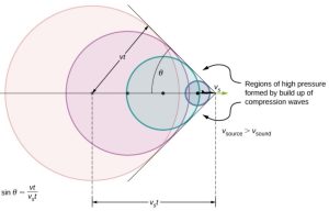
Where:
t = time
s = source
v = velocity
Note: “Sound waves from a source that moves faster than the speed of sound spread spherically from the point where they are emitted, but the source moves ahead of each wave. Constructive interference along the lines shown (actually a cone in three dimensions) creates a shock wave called a sonic boom. The faster the speed of the source, the smaller the angle θ”. (Lumen Learning, 2018).” .
Sourced from: https://s3-us-west-2.amazonaws.com/courses-images/wp-content/uploads/sites/2952/2018/01/31201658/CNX_UPhysics_17_08_SBoom.jpg
When an object travels at hypersonic speeds, it generates a bow shock wave in front of it. This bow shock wave is a curved shock wave that forms as the object’s leading edge compresses the air ahead of it and marks the boundary between the supersonic flow ahead of the object and the compressed, subsonic flow around it.
Behind the bow shock wave exists a compressed air region called the shock layer or shock wave boundary layer. This region experiences high temperatures and pressures due to the compression caused by the shock wave. The shock layer is characterized by sudden air density, temperature, and pressure increase.
In addition to the bow shock wave, hypersonic flight can also produce other shock waves depending on the shape and characteristics of the object. For example, if the object has sharp leading edges or prominent features, additional shock waves called detached shocks, or compression shocks can form at those locations.
Figure 13-5
Shock And Compression Waves
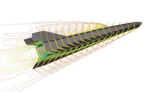
Note: ”Passing the speed of sound compresses air flowing over an airfoil, creating a shockwave.- the “sonic boom” Waveriders use the shockwave to increase their lift, essentially surfing on a wave of pressurized air.” ” (U.S. Naval Institute, 2020)
Sourced from: https://www.usni.org/magazines/proceedings/2020/december/hypersonic-missiles-coming-hot
The presence of shock waves in hypersonic flight has several implications. First, shock waves contribute to thermodynamic heating, primarily caused by converting the object’s kinetic energy into thermal energy as it pushes through the air. As the object moves faster than the speed of sound, it compresses the air in front of it, increasing air pressure and temperature. As the object’s speed increases, this compression-heating effect becomes more pronounced.
The process of thermodynamic heating involves several factors:
Compressibility: At hypersonic speeds, the compressibility of the air becomes significant because the air cannot respond instantaneously to changes in pressure, resulting in local increases in temperature. This compression heating is related to the adiabatic heating of the gas as it is compressed.
Frictional Heating: The interaction between the object and the surrounding air generates frictional forces. These forces convert kinetic energy into thermal energy, leading to further heating. The heat generated by friction depends on the object’s surface properties, such as its roughness and material composition, as well as the density of the material being traveled through, in this case, air.
Shock Wave Heating: Shock waves form when objects move at hypersonic speeds. These shock waves compress the air and create high-pressure and temperature regions, contributing to the object’s overall thermodynamic heating.
The high temperatures resulting from the thermodynamics of heating created by hypersonic flight pose significant challenges to the design and materials used in and on such vehicles. For example, extreme heat can cause structural deformation, material degradation, comprise electronic components, and cause thermal stresses. Therefore, advanced materials, such as ceramics and Thermal Protection Systems (TPS), are often used to manage and dissipate heat, protecting the vehicle’s structure. The following are some broad temperature ranges. Please note that these ranges will change based on vehicle design and other conditions:
Low Hypersonic Speeds (Mach 5 to Mach 7): At these speeds, the temperatures experienced can range from approximately 900°C to 1,500°C (1,650°F to 2,730°F). This range represents the compression heating and frictional heating effects caused by the object’s interaction with the air.
Intermediate Hypersonic Speeds (Mach 7 to Mach 12): In this speed range, due to increased compression and frictional heating, temperatures can range from approximately 1,500°C to 2,500°C (2,730°F to 4,530°F). These temperatures are more demanding on coverings materials and airframes of hypersonic vehicles’ and their thermal protection systems.
High Hypersonic Speeds (Mach 12 and above): At very high hypersonic speeds, temperatures can exceed 2,500°C (4,530°F) and can potentially reach up to 3,000°C (5,432°F) or even higher. The specific temperatures depend on the vehicle’s design and the effectiveness of its thermal protection systems.
To help illustrate the heat intensity generated at these speeds, the following table provides the melting temperatures of various metals to act as a general reference to illustrate the heat generated by a hypersonic thermal activity.
 Source: (American Element, 2022)
In addition to heating, shock waves can lead to increased drag and aerodynamic forces, affecting the vehicle’s stability and control, which can also cause fluctuations in the aerodynamic forces and induce vibrations or buffeting, which must be carefully considered in the vehicle’s design.
ADVANCEMENTS IN METALLURGY AND HEAT DISSIPATING MATERIALS
The thermodynamics introduced by compressibility, frictional drag, and shock wave heating occurring at hypersonic speeds make it imperative that hypersonic missiles be made from materials that can withstand the extreme heat and pressure generated by their extraordinary speeds. Recent advancements in materials science have led to the development of new compounds and compositions that can withstand many of these conditions. Over the past decade, there have been advancements in:
Carbon-Carbon Composite: Carbon-carbon composites are carbon fibers embedded in a carbon matrix. They possess excellent thermal stability and can withstand temperatures up to 3,000 degrees Celsius (5,432 °F). These composites are lightweight, strong, and commonly used in aerospace applications.
Ceramic Matrix Composites (CMCs): CMCs combine ceramic fibers and a ceramic matrix. They exhibit high strength and excellent thermal resistance. CMCs can withstand temperatures exceeding 2,000 degrees Celsius (3,632 °F). They are lighter than traditional metals and are being researched for use in hypersonic vehicle structures.
Refractory Metals: Certain refractory metals, such as tungsten and molybdenum, have high melting points and can withstand extreme temperatures. Tungsten, for example, has a melting point of approximately 3,400 degrees Celsius (6,152 °F). These metals are often used in aerospace applications requiring resistance to high temperatures.
Nickel-Based Superalloys: Superalloys are high-performance alloys that maintain strength at high temperatures. Nickel-based superalloys, such as Inconel and Hastelloy, display excellent resistance to heat and oxidation. They are commonly used in the hot sections of jet engines and can also be considered for hypersonic applications.
Graphene: Graphene is a single layer of carbon atoms arranged in a hexagonal lattice. It has exceptional mechanical, thermal, and electrical properties. Graphene can handle high temperatures and has excellent thermal conductivity. However, it is still in the early development and large-scale production stages.
If one were to review the history of high-speed flight, one could observe the changes that have occurred over time with the increase in speed and the need for improved materials.
Figure 13-6
Improvements In The Use Of Various Materials For Heat Dissipation

Source: (Glass, 2015)
This chapter only covers a few areas currently developing materials for hypersonic applications. This is an arena of active research with new materials and composites constantly being explored.
In addition to improving heat tolerance, it is critical to dissipate heat through Thermal Protection Systems (TPS) improvements via more advanced protective materials and techniques. Heat dissipation is usually addressed via aerodynamic/structural design and the implementation of effective Heat Management Systems (HMS) that quickly redistribute heat to protect airframes and electronic instruments. This becomes a critical engineering challenge due to the rapid changes in pressure and temperature that can pose significant risks to electronic components. For example, almost all electronic components are joined with a form of solder. One such solder is Eutectic Gold Tin “(Gold-tin (AuSn) solder is a eutectic alloy composed of 80% gold and 20% tin by weight, with a melting point of 280°C (536°F).” (Electricity – Magnetism, 2023). Other specialized alloys are reported to have melting points of 1000 degrees Celsius (1,832°F) in brazing applications. In the situation with Eutectic Gold Tin “(Gold-tin (AuSn) solder, if the internal temperature exceeded the melting point of 280°C (536°F), the solder would begin to melt and loosen the connections between components. This is just one example, but other components are also directly affected by heat. Fortunately, decades of information collected for satellite research, development, and actual launches, have derived many operational limits for instrumentation. However, regardless of the structure’s heat resistance to melting, “The maximum structure temperature is still far higher than the temperatures that would cause degradation and failure to electronic components…Components can be subjected to temperatures as low as –55°C (–67°F) and as high as 125°C (257°F)… These thermal conditions induce several failure modes, including package and die cracking, bond-wire breakage, moisture ingress, die delamination, tin whisker growth, and solder-joint failure.” (Electronic Products, 2019).
Figure 13-7 Comparative Speeds and Temperatures

Note: The temperature will vary based on the material and aerodynamic design of the vehicles.
As illustrated in the above chart, thermal management must be applied and maintained to ensure the instrumentation needed for computation, navigation, directional control, communications, and other management functions are not compromised.
Heat Management Systems (HMS) research has expanded in many areas to address challenges discovered due to heat generated from hypersonic velocities. These systems are designed to dissipate or absorb excessive heat, prevent damage to critical components and ensure the missile’s performance. The following are a few examples:
Heat Sinks and Radiators: Heat sinks and radiators dissipate excess heat from critical components. These systems typically use high-conductivity materials and structures, such as heat pipes or cooling fins, to absorb and transfer heat from sensitive areas. Radiators provide a surface for heat to radiate into the surrounding environment, helping to cool down the missile.
Active Cooling: In some cases, hypersonic missiles utilize active cooling techniques to manage heat. This can involve circulating a coolant, such as a liquid or gas, through channels within the missile’s structure to absorb and carry away heat from critical components. Active cooling systems, though more complex, can provide efficient heat transfer and enable sustained operation under high-temperature conditions.
Insulation: Insulation materials are used to minimize heat transfer between the hot exterior environment and the internal components of the missile. Multi-layered insulation (MLI) blankets or other low-thermal-conductivity materials create a thermal barrier and protect sensitive components from excessive heat exposure.
Thermal Management Design: The overall design of the missile, including its shape and configuration, is optimized to manage heat. By carefully shaping the missile’s body and incorporating aerodynamic features, it can help control the intensity of heat generated during flight and minimize its impact on critical components.
Figure 13-8
Examples Of Various Cooling Techniques
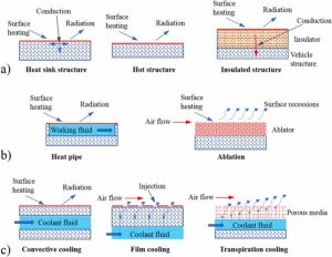
Source: (Le, Ha, & Goo, 2021)
Of particular interest for sustained hypersonic flight are the various types of active cooling systems; some hypersonic missiles may employ active thermal control systems that use advanced techniques to manage heat. These systems can include various methods, such as regenerative cooling, film cooling, and other cooling technologies, to effectively control the temperature and protect critical components:
Regenerative Cooling: Regenerative cooling is a common active cooling technique in hypersonic missiles. In this method, a coolant, such as liquid hydrogen or fuel, is circulated through channels or tubes in the missile’s structure, typically around the combustion chamber or nozzle. The coolant absorbs heat from the hot surfaces and then passes through a heat exchanger to cool down before being recirculated. This continuous circulation of the coolant helps maintain the temperature within acceptable limits.
Film Cooling: Film cooling is another active technique employed in hypersonic missiles. It involves the release of a thin film of coolant, usually a liquid or gas, over hot surfaces. The coolant forms a protective layer that helps reduce the heat transfer to the structure. The coolant film can be sprayed from small orifices or delivered through porous materials on the missile’s surface.
Transpiration Cooling: Transpiration cooling involves using porous materials or coatings on the missile’s surfaces. Coolant is supplied to the porous material, which then permeates through the material and evaporates on the outer surface. This evaporation absorbs heat from the surface, effectively cooling it.
The specific cooling system used in a hypersonic missile depends on various factors, including the missile’s design, materials, operating conditions, and mission requirements. Each cooling system has advantages and limitations, and the choice of the cooling technique is determined by weight, complexity, and reliability and will require performance trade-offs.
Progress in airframe design and maneuverability
Recent advancements have focused on increasing maneuverability by making vehicles more agile. This agility will aid in avoiding enemy defenses and better enable them to hit their targets more accurately. Some notable improvements in this area have been:
Aerodynamic Shape Optimization: Advanced computational fluid dynamics (CFD) techniques, combined with powerful computing resources, allow for detailed analysis and optimization of the airframe’s shape. This involves refining the vehicle’s external contours to minimize drag and enhance aerodynamic efficiency at hypersonic speeds. Improving the vehicle’s aerodynamic shape helps reduce heat generation and enables more efficient propulsion.
Maneuvering and Control Systems: Hypersonic vehicles require advanced maneuvering and control systems to navigate the challenging flight demands. Developing advanced flight control algorithms, reaction control systems, and aerodynamic control surfaces enables better maneuverability, stability, and control authority during hypersonic flight. These systems allow for precise trajectory control, maneuver execution, and vehicle stability.
Variable Geometry: Some hypersonic airframe designs incorporate variable geometry features, such as adjustable wings or control surfaces. Variable geometry allows the vehicle to optimize its configuration based on different flight conditions, including changing aerodynamic forces, center of gravity, and stability requirements. This flexibility enhances performance and control across various flight conditions or requirements.
Active Flow Control: Active flow control techniques involve manipulating the airflow around the airframe using sensors, actuators, and intelligent control systems. These systems can enhance aerodynamic efficiency, reduce drag, and improve stability and control by manipulating boundary layer flow or employing adaptive control surfaces. Active flow control enables better vehicle response, improved maneuverability, and increased overall performance.
Integrated Vehicle Design: Advancements in hypersonic vehicle design involve considering the vehicle as a whole system rather than individual components. To achieve overall performance improvements, integrated vehicle design approaches optimize the interactions between various subsystems, such as aerodynamics, propulsion, structures, and controls. This holistic design approach ensures efficient use of resources, minimizes weight, maximizes performance, and enhances maneuverability.
The concept of Variable Geometry, also known as Morphing airframes, is a product of the holistic design approach. It refers to the design and technology that allows for changes in the shape or configuration of an aircraft’s structure during flight. This capability offers several potential benefits, including improved aerodynamic performance, increased maneuverability, reduced drag, enhanced fuel efficiency, and adaptability to varying flight conditions. Here are some key aspects and examples of morphing airframe technologies:
Shape-Changing Structures: Morphing airframes incorporate structures that can change shape or configuration to optimize performance. This can involve using flexible and intelligent materials or mechanisms for controlled deformation. For example, variable camber wings can change the curvature of the wing surface to improve lift characteristics and control.
Adaptive Wing Morphing: Adaptive wing morphing focuses on changing the wing shape to adjust to different flight conditions. This can include altering wing sweep, span, chord length, or twist. By adjusting the wing’s geometry, aircraft can optimize their performance across various flight conditions, from subsonic to supersonic or hypersonic speeds.
Active Flow Control: Morphing airframes can incorporate active flow control technologies, such as synthetic jet actuators or fluidic devices, to manipulate the airflow over the aircraft’s surfaces. These devices can create localized changes in airflow patterns, reduce drag, enhance stability, and improve control authority.
Shape Memory Alloys (SMAs): SMAs can undergo deformation and return to their original shape when subjected to specific stimuli, such as electrical or temperature changes or mechanical stress. By integrating SMAs into the airframe structure, components can change shape or position in response to different flight conditions.
Distributed Control Systems: Morphing airframes require sophisticated control systems to monitor flight conditions and adjust the shape or configuration of the aircraft accordingly. These systems often use sensor arrays, computational algorithms, and actuators to enable real-time adjustments to provide safeguards and ensure optimal performance.
Biomimicry: Morphing airframe designs can draw inspiration from nature, imitating the adaptive features of birds, insects, or marine animals. For instance, the ability of birds to change wing shape during flight has inspired the development of biomimetic morphing wing designs.
Figure 13-9
Morphing Wings And Airframes
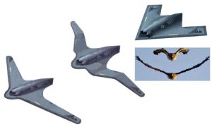
Note: Different morphing configurations can provide the ultimate configuration relative to the action performed. The above image has standard flight, Lottering, and dash configurations.
Adapted from: https://trimis.ec.europa.eu/sites/default/files/project/documents/40418/final1-maws-overview.pdf (Yang, Nangia, & Cooper, 2014)
Morphing airframes are a promising research area in the early stages. However, as previously stated, these require continued study and advancements in materials science, control systems, and manufacturing techniques to enable a morphing airframe that could meet military demands.
ADVANCEMENTS IN COMPUTER DEVELOPMENT AND ARTIFICIAL INTELLIGENCE (AI)
Developing computers for hypersonic missiles is crucial in achieving the desired performance, accuracy, and responsiveness intended for such weapons. Achieving such will require sophisticated onboard computers to handle real-time complex tasks. The following are some critical aspects of computer development that will be impacting to the advancement of hypersonic missiles:
Radiation-Hardened Processors: Hypersonic missiles often operate in environments with high radiation levels, such as during space travel or atmospheric re-entry. To ensure the reliability of onboard electronics, radiation-hardened processors are used. These processors are designed to withstand the effects of radiation and prevent malfunctions caused by radiation-induced errors.
High-Performance Processors: The need for powerful processors capable of executing complex algorithms quickly and accurately are required for hypersonic activity. These processors must handle navigation, guidance, control, and sensor data processing tasks at extremely high speeds. Specialized high-performance computing architectures such as Multi-Core Processing are often employed to meet these requirements.
Real-Time Operating Systems: To ensure timely execution of critical functions, hypersonic missiles typically use real-time operating systems (RTOS). RTOS prioritizes tasks based on their urgency, minimizing the possibility of delays, and ensuring precise control and responsiveness during flight. Some RTOSs allow for separating critical and non-critical software components, enabling the coexistence of multiple operating systems or applications on the same hardware platform.
Navigation and Guidance Algorithms: Sophisticated navigation and guidance algorithms are essential for hypersonic missiles to maintain their intended trajectory and accurately hit their targets. These algorithms continuously analyze sensor data, such as GPS signals and inertial measurements, to compute optimal flight paths and adjust course corrections in real time.
Sensor Fusion: Hypersonic missiles rely on various sensors, such as inertial measurement units (IMUs), GPS receivers, and advanced imaging or target-tracking sensors, to gather data about their surroundings and targets. Sensor fusion algorithms integrate information from these diverse sources to enhance situational awareness and improve the missile’s ability to identify and engage targets.
Autonomous Decision-Making: Hypersonic missiles often operate in contested and rapidly changing environments. As a result, they may need to make autonomous decisions to adapt to unexpected scenarios or countermeasures. Advanced artificial intelligence (AI) and machine learning algorithms are integrated into missile computers to provide intelligent decision-making capabilities.
Figure 13-10 Sample Of High-Level Architecture For U Coupling With A Refueling Drogue Coupling
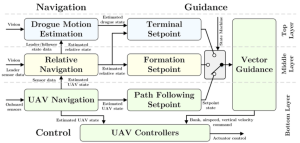
Note: This does not represent the far more complex architecture and sub-systems that would provide services for a hypersonic vehicle but gives a general idea of activities that must be accounted for.
Adapted from: (Wilson, 2015)
Secure Communication: Hypersonic missiles may communicate with command centers or other platforms during flight, requiring secure and robust communication systems to relay data and receive updated instructions. Encryption and secure communication protocols are essential to protect the missile’s integrity and maintain operational security. In addition, the encryption/decryption process must be performed quickly to avoid introducing delays in the Communication, Command, and Control(C3) flow. The systems must also account for the ionization surrounding the vehicle at such speeds.
Fault Tolerance and Redundancy: Exposure to extreme conditions and challenging environments makes it necessary for onboard computers to incorporate fault-tolerant design principles and redundant surface control systems to improve the reliability of mission success. This redundancy enables the missile to continue functioning even if specific components fail during flight.
Although much of the information related to the types of processors used is classified, they must have high-performance computing capabilities to perform real-time processing from the many sensors needed for vehicle operation and make real-time calculations for precision maneuver execution. For example, at Mach 5, a missile will travel approximately 1 mile a second. There is no time for delayed calculations or signal delivery to critical maneuvering components. Such development is a multidisciplinary endeavor involving aerospace engineering, computer science, electronics, system integration, and manufacturing expertise.
Figure 13-11
Cutaway Diagram of the X-51A HCM with Subsystems
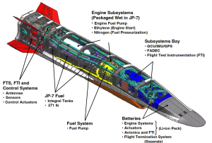
Source: J. Hank, J. M., Murphy, J. S. and Mutzman, R. C., ‘The X-51A Scramjet Engine Flight
Demonstration Program’, 15th AIAA International Space Planes and Hypersonic Systems and
Technologies Conference, May 2008, p. 7., (J. Hank, 2008)
In addition, to improve computing hardware. It is crucial that the software be equally as efficient and can perform exceptional analytics. Artificial intelligence (AI) plays a role in various aspects, including guidance, navigation, control (GNC), target acquisition, and autonomous decision-making. Here are some specific AI uses in hypersonic missiles:
Data Processing and Fusion: Vast quantities of data are generated from onboard sensors and external sources. AI can assist in processing and fusing this data to provide a comprehensive situational awareness for the missile’s guidance and decision-making systems. Machine learning algorithms can integrate and analyze information from multiple sources to generate accurate and real-time assessments for flight duration.
GNC Optimization: AI can optimize hypersonic missiles’ guidance, navigation, and control algorithms to enhance flight performance and accuracy. Machine learning techniques can analyze vast data to improve trajectory planning, control surface adjustment, and overall flight stability.
Target Recognition and Tracking: AI can analyze sensor data, such as radar and infrared imaging, to detect, identify, and track targets. Machine learning algorithms can recognize patterns and signatures associated with various types of targets, improving the missile’s ability to acquire and engage them. This same technology is beneficial in countermeasures used to detect hypersonic missiles during various stages of flight.
Autonomous Targeting: AI can autonomously select and prioritize targets based on predefined criteria. Integrating AI algorithms into the missile’s system allows it to analyze real-time data, assess threats, and make decisions on target engagement without human intervention.
Countermeasures and Adaptability: Hypersonic missiles must evade potential enemy defenses and react to changing scenarios. AI algorithms can assess and respond to incoming threats, identify countermeasures, and adapt the missile’s trajectory or tactics accordingly. This adaptability can enhance the missile’s survivability and increase the likelihood of mission success.
Figure 13-12
Detection avoidance
Source: (Brimelow, 2018)
AI applications augmented with machine learning have the potential to evade enemy countermeasures and reconfigure themselves based on current circumstances and situational awareness. This capability will allow the device to react to unplanned encounters and revise operational requirements based on current environmental and available operational information or decide without such data.
ENHANCEMENTS TO DELIVERY SYSTEMS
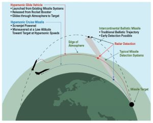
To appropriately frame the concept of hypersonic missiles, it is essential to understand that there are two major categories, each of which can be deployed from multiple platforms, such as air, ship, land, or space. As discussed in Book 7, chapter 2 on Satellite Killers and Hypersonic Drones (2022), there is the Hypersonic Cruise Missile (HCM) has a self-contained propulsion system, typically driven by SCRAM jet technology and Hypersonic Glide Vehicle (HGV), relies on gravity and atmospheric conditions to produce speed and maneuverability. These vehicles are difficult to track if released from an aerial or space platform.
Figure 13-13
Categories of Hypersonic Missiles

Source: The RAND Corporation (Speier, Nacouzi, Lee, & Moore, 2017)
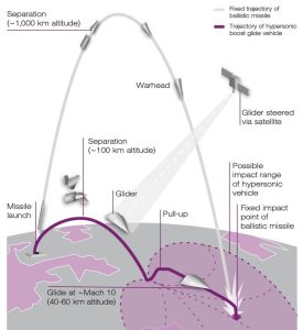
Unlike their predecessor, the ballistic missile, which follows a parabola-shaped arch and has a predictable flight path from launch to target.
Figure 13-14
Sample Ballistic Missile Trajectories
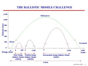
Source: (Salia, 2018)
The hypersonic HCM and HGVs operate on a flatter trajectory and are more maneuverable. Their agility provides a more capability to avoid detection by terrestrial-based radar and a higher probability of evading opposition countermeasures if deployed. Improvements in navigation, guidance, and control technology make it possible to seek alternate targets within its strike range and even calculate flight paths that would introduce confusion into opposition tracking used to detect and calculate the probability of which locations may be potential targets. This type of deception would help impede the opposition’s ability to deploy countermeasures to protect the actual target.
Figure 13-15
Points Of Terrestrial Detection of HCM, HGV, and Ballistic Missiles
Source: (Higham & Strategy_Analytics, 2022)
Figure 13-16
Possible Alternate Target Options of an HCM or HGV
Source: (Delcker, 2019)
As with any weapon system that takes flight, weight and flight characteristics become a consideration in the design, operational range, and speed. For example, both designs require some initial level of flight assistance. HGVs frequently require assistance from a booster to achieve low orbit and utilize gravity. In the case of HCMs, a booster or air launch is necessary to obtain the speed required to engage the onboard SCRAM jet engine. Also, the HCM must carry its fuel and other needed control systems and payload it would deliver. Advancements in rocket boosters, electronics, lightweight, heat-resistant material, and aerodynamic designs have made it possible to carry larger payloads, either nuclear or conventional.
The advent of aeronautical advancements such as the Space Shuttle and Space-X have removed obstacles that once rendered consideration of some previous concepts cost prohibitive or just unfeasible. These more contemporary advancements and technical improvements have opened the door for reconsidering old concepts based on applying advancements in other areas. For example, there is renewed interest in space platforms such as “Project Thor” or “Rods from God,” which refers to creating a space-based weapon system involving kinetic bombardment. The concept is to use the gravitational force to accelerate a large rod or projectile, typically made of dense materials like tungsten, that would generate significant destructive power upon impact with a target on Earth. Once launched from an Orbital Kinetic Energy Bombardment Platform, tungsten rods of 20-foot lengths by 1-foot diameters and traveling at approximately Mach 10 would have sufficient Kinetic Energy to cause mass destruction (Stilwell, 20211).
To provide context, given that the rod has a diameter of 1 foot (0.3048 meters) and a length of 20 feet (6.096 meters) and is constructed of tungsten, we can calculate the weight as follows:
Radius = diameter / 2 = 0.3048 / 2 = 0.1524 meters
Volume = π * (0.1524^2) * 6.096 = 0.554 cubic meters
Weight = Volume * Density = 0.554 * 19,250 = 10,676.75 kilograms
The tungsten rod would weigh approximately 10,676.75 kilograms (or approximately 10.68 metric tons).
The Kinetic Energy produced at this weight coupled with a speed of Mach 10 would produce:
Velocity = 10 * 343 (Mach 1) = 3,430 meters per second
Converting the mass of the tungsten rod to kilograms (~10.7 metric tons = 10,700 kilograms)
Kinetic Energy = (1/2) * 10,700 kg * (3,430 m/s)^2
Kinetic Energy ≈ 248,594,050,000 joules or 248.6 gigajoules
To add perspective, one ton of TNT is equivalent to 4.184 gigajoules. Therefore, the energy from the 20-foot rod would be equivalent to 59.4 metric tons of TNT. This would be slightly more than the 6.4 magnitude earthquake that hit off the coast of Puerto Rico on January 6, 2020, causing widespread devastation to the southern region. This concentrated amount of kinetic energy converted to potential energy in milliseconds would have a devastating impact. Estimations would have the rod at said weight and speed with a 50–60-degree angle of impact, could displace approximately 23,700 cubic meters of earth, generate intense heat, and leave an impact creator approximately 49-meters (161.75 ft) wide and 12.3 meters (40.35 ft) deep. This would not account for the damage created by shockwaves, flying debris, or EMP generation and would leave virtually no radioactive fallout.
Figure 13-17 THOR

Image from: Kebal Space Program Forums / LADBible (SOFREP, 2022)
Figure 13-18 Chinese Reported a test drop of KE HGV
Source: (China Arms, 2020)
REVISIONS IN DEFENSIVE STRATEGIES
The continued multi-discipline improvements refining hypersonic technology have made it difficult, at best, to detect and neutralize weapons employing these technologies. This provides for offensive superiority even if the defending side has offensive parity unless the defending side has developed appropriate countermeasures; even then, because of the speeds involved, target acquisition capabilities, and maneuverability of these weapons, it may nullify any reaction time of the defender. Therefore, defensive detection methods must be enhanced to provide quicker and more reliable notifications/alerts to increase the probability of neutralizing such a threat. As discussed earlier in the chapter, the Observe, Orient, Decide, Act (OODA) loop is a primary methodology for evaluating subsequent actions and acting on them. The sooner the steps of observation and orientation are accomplished, the more time is available to decide and act.
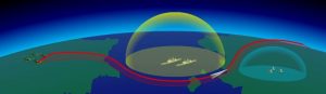
As with the innovations in computer technology, Real-Time-Operating-Systems (RTOS) and AI are assisting with hypersonic-based delivery systems; the same or similar technology can aid in its detection and implementation of countermeasures. We discussed how technological advances such as the Space Shuttle and Space-X can enable the delivery of platforms like the “Thor Project.” These have also enabled innovations in early observation/detection. Such innovation will help improve the “Observe” phase of the OODA loop. Since 2019 The Pentagon’s Space Development Agency (SDA) has been actively partnering with Northrop Grumman, York Space Systems, L3Harris, and Space-X to architect and deploy a U.S. military mega-constellation consisting of hundreds of small satellites to improve the detection of hypersonic missiles. Before advancements in booster technologies, capabilities to reuse a booster, and the ability to return to the launch pad, deployments of such scall were not achievable. Such technological advancements have made it technically and financially feasible to field a network of space-based monitoring and communication satellites to provide a virtual canvasing of the entire globe.
Figure 13-19 Plans For A U.S. Military Mega-Constellation
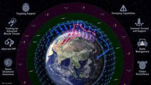
Photo: US Department Of Defense,
Source: https://www.defense.gov/Multimedia/Photos/igphoto/2002511880/
These new networks of satellites equipped with new sensor technology can detect new Infrared signatures and pierce the armor of plasma stealth. In many cases, as the missile reaches such high velocities, it experiences extreme aerodynamic heating due to air compression, leading to a plasma cloud around the missile. Plasma stealth, also known as active plasma-based stealth, is a proposed technique for reducing the radar detectability of an aircraft or missile by creating a plasma cloud around it.
The idea behind plasma stealth is to use the high temperatures generated by the hypersonic flight to create a layer of ionized gas, or plasma, around the missile. This plasma cloud could interfere with radar signals and reduce the missile’s detectability. The ionized gas would reflect, absorb, or scatter the incoming radar waves, making it more difficult for radar systems to detect and track the missile accurately.
The exact speed at which a plasma cloud forms can vary, but it generally occurs from Mach 7 to Mach 10 (approximately 2,390 to 3,430 meters per second at sea level). At these speeds, the air surrounding the missile becomes so highly energized that the electrons and ions dissociate from their atoms, forming a conductive plasma.
Although Plasma Stealth can provide a viable stealth value from radar to such missiles, the ionization of air that provides this stealth can itself be detected because it will leave a Plasma footprint which, although is shortly lived (milliseconds), can be detected from satellites property equipped (Harshitha & Baskaradas, 2023). As discussed, the legacy technology was optimized for launching and tracking ICBMs with satellites that would detect the large plums and exhaust from silos and ground-based radar sensitive to the distinct heat signatures and radar reflections of
Figure 13-20
Mesh Network Of Satellites in a Constellation
Source: (Tingley, 2021), Photo: US Department Of Defense’s SDA
Such missile launches.
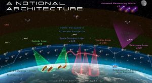
LAYERED DEFENSE
Due to new technology in the area of Electro-optical Infrared (EO/IR), it is possible to detect hypersonic missiles transitioning from glide to terminal phases of their flight profiles. In addition, the development of a Space-Based Infrared System (SBIRS) and Hypersonic and Ballistic Tracking Space Sensor (HBTSS), in a constellation configuration, can perform detections from the moment of launch and track the missile to completion. Advancements in AI are aiding in friend-or-foe identification, Battle Management, Communication, Command, and Control. The combination of these technologies will be part of a multi-layer defense strategy. This would include surveillance and early warning systems that are radar and space-based and would include ground-based units equipped with inceptors and various types of Direct Energy Weapons (DEW). Such a defense strategy would incorporate advanced battle management systems to coordinate and integrate various data collection platforms, including air and sea-based reconnaissance. This integrated information collection would provide a comprehensive real-time situational picture providing the essential information necessary for critical decision-making. Because of the speed associated with hypersonic weapons, it may be necessary to have AI incorporated into the intercept decision-making process. Such a need will be dictated based on when the missile was detected and its distance from any assets within the range of potential attack vectors.
Figure 13-21
Layered Detection, Tracking, And Intercept
![]()
Source: (Burgess, 2022) Photo: Northrop Grumman
The end-to-end time to iterate through the OODA loop decreases as technology advances. The recently discussed topics help improve the ability to ”Observe” a launch. With the aid of advanced computer algorithms and inputs from other sources and space-based systems, it, and proper integration of battle management systems, it is possible to “Orient.” much quicker. However, it is critical to have sufficient information to “Decide” and “Act.” This may require another set of technologies that will perform predictive analytics based on collected information from the previously discussed data collection points to make informed decisions in predicting the probability of where a hypersonic vehicle may be targeting. This becomes complicated since the devices are so fast and agile that there may not be sufficient time to decide to intercept, evacuate, or accept the collateral damage. This may be further impacted by onboard intelligence of the oncoming weapon. It is feasible that the attacking device may have similar built-in intelligence to thaw or counter any attempts by the defender to analyze or compute an intercept and therefore consume additional time. All such tactics can incur additional delays in the “Decision” making process, not to mention political implications, both national and international, which may be a further hindrance. However, in a pure combat theater, such as shore-to-ship attacks, or ground support operations, such a decision may be made quicker with AI, and in combat scenarios, attacks are usually focused on military or war-supporting assets. However, it should be noted that there are significant moral and ethical concerns surrounding using AI systems to make autonomous launch decisions. Most militaries worldwide require human intervention and oversight to authorize a missile launch.
Figure 13-22 Layered Detection And Defense
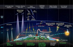
Source: (CSIS, 2019), Photo: Missile Defense Agency
Note: With Overhead Persistent Infrared (OPIR) satellites, improved communications, and AI, it is possible to perform integrated battle management and intercept activities more expediently.
INTERCEPT AND DEFENSE CAPABILITIES
The final step in the OODA loop is to act once a decision is made. At this point, a critical portion of the time to act has been consumed in the previous three steps of the process. The final step also takes considerable time because physical activities include target acquisition, development of a firing solution, launch, and travel time to a plotted intercept location of the agile target, traveling at Mach 5 or greater. As previously mentioned, this type of interception calls for a multi-layered and integrated defense strategy. The strategies include current and future intercept capabilities
- Surface-To-Air missiles, which include ship-based missile systems.
- Direct Energy Weapons (DEW), which fall into the general groupings of
Particle Beam Weapons: Consist of a beam of high-energy particles.
Microwave-Based: Designed to produce electromagnetic interference
LASER-based: Designed to heat or pulse a target and destroy critical parts
LIPC weapons: Laser-Induced Plasma Channel makes a channel to allow clear passage of an electromagnetic stream to the target.
Currently, the arsenal of fielded aerial defensive weapons is limited to such systems as RIM-161 or SM-3 class missiles. Such limits make the ability to detect, track and communicate timely extremely important.
Figure 13-23 Hypersonic Surface-To-Air Inceptor Missile

Source: (CSIS, 2023)
Development of additional land and sea-based systems, such as electromagnetic railguns (EMRG) that would catapult a gun-lunched guided projectile (GLGP) or hypervelocity projectile (HVP), are actively being explored and tested.
As outlined in the April 21, 2023, report to Congress, which discussed concerns regarding navel vulnerabilities with existing shipboard defense systems, it was suggested that investments be made in ship-based Solid-State Laser(SSL) technology. This has led to the development of the Navy Laser Family of Systems, which include such projects as Advanced Test High Energy Asset (ATHENA), High Energy Laser Counter-ASCM Program (HELCAP), and the development of the High-Energy Laser with Integrated Optical Dazzler and Surveillance (HELIOS) weapon systems (CRS, 2023).
In addition to laser-type technologies, there are many advancements in using High-Power Microwave systems to perform Counter-Electronic activity. Such systems would damage the electronics of an adversary’s weapons and Electronic Warfare and Countermeasure systems, including navigation, in which the microwaves would jam or disrupt communications and other functionality essential to operate the attacking weapon adequately. This is currently being pursued in an effort known as CHAMPS (Counter-Electronics High Power Microwave Advanced Missile Project) and has been stated as deployed on one or more naval vessels for testing and evaluation.
Figure 13-24 Stated ODIN System aboard USS Stockdale
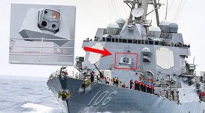
Source from: (Tingley, 2021) https://www.thedrive.com/the-war-zone/41525/heres-our-best-look-yet-at-the-navys-new-laser-dazzler-system
This technology has also been demonstrated in the Tactical High-power Operational Responder (THOR), in which swarms of UAS were neutralized with microwave transmissions.
Figure 13-25 THOR Microwave DEW system

Sourced from: https://www.airandspaceforces.com/air-forces-thor-drone-swarm-demo/
It should be noted that more highly powered systems are under development to neutralize the threats imposed by hypersonic missiles. However, in the interim, there are fielded systems that can eliminate more minor threats and attacks from UAS. In many situations, an adversary would implement strategies that deplete a ship’s aerial interceptor inventory or munitions supporting the Close-in Weapon Systems (CIWS). Once inventory is depleted, known as “limited depth of magazine,” a ship would be virtually unprotected. This scenario has been realized with the use of swarms. Although not at the scale necessary to eliminate significant threats such as missiles, the use of Direct Energy (DE) weapons would assist with the elimination of more minor threats, such as drones, and maintain the consumable assets for the more significant threats, such as a hypersonic missile attack.
SUMMARY
Hypersonic weapons are real and have been in existence since the 1960s. As technology has advanced, so has the ability to develop and field more advanced weapons. However, the types of hypersonic weapons the current world powers boasted about continue to partially defy the physics and currently available materials and technology to support the brags, boast, and hype. However, research into heat-resistant compounds, streamlined aerial designs, computer components, sensor development, satellite constellations, combat management systems, and Artificial Intelligence continue to bring these aspirations into the realm of feasibility and continue to improve the first-strike dominance of whom every achieves such. Likewise, the same multi-discipline technological advancements are being undertaken to develop countermeasures to neutralize such attacks to maintain a balance of power.
Overall, the advancements in hypersonic missile technology are making these weapons even faster and more effective. The continued development also raises concerns about the risks of accidental or intentional use and the potential to destabilize the concept of offensive parity and mutually assured destruction as deterrents. Due to the sheer speed and agility of hypersonic weapons, which will only become faster and more maneuverable, will be required nations to adopt new strategies that may require launch decisions to be made by AI as opposed to humans intervention and the adoption of revised launch-on-detection (LOD) policies where the defender must launch any countermeasure and retaliatory actions on detection of what is perceived to be an enemy’s launch as a last-ditch effort to provide the highest probability of survival. Such strategies will continue to heighten tensions and fuel the inevitable cycle of competitive superiority.
REFERENCES
AE Toolbox. (2022, Mar 31). Melting Points for 10 Common Metals. Retrieved from www.americanelements.com: https://www.americanelements.com/meltingpoint.html
Aero Corner . (2021, June 15). 13 fastest fighter Jets in the world (+ 4 fastest jet aircraft). Retrieved from https://aerocorner.com/blog/fastest-fighter-jets/: https://aerocorner.com/blog/fastest-fighter-jets/
American Element. (2022, March 31). Melting Point of Common Metals, Alloys, & Other Materials. Retrieved from americanelements.com: https://www.americanelements.com/meltingpoint.html
AstriaGraph. (2022, August 14). Realtime Satellite and Debris Map. Retrieved August 14, 2022, from astria.tacc.utexas.edu: https://astria.tacc.utexas.edu/AstriaGraph/
Blair, B. G. (2019, Oct). The U.S. Nuclear Launch Decision Process (on warning of incoming Russian missile). Retrieved from www.globalzero.org/: https://www.globalzero.org/wp-content/uploads/2020/11/Full-LOWTimeline.pdf
Brimelow, B. (2018, April 30). Russia, China, and the US are in a hypersonic weapons arms race — and officials warn the US could be falling behind . Retrieved from www.businessinsider.com: https://www.businessinsider.com/hypersonic-weapons-us-china-russia-arms-race-2018-4
Burgess, R. R. (2022, February 2). ice Adm. Hill: MDA Pushes Space-Based Sensor for Tracking Hypersonic Missiles for Fleet Defense . Retrieved from SeaPower: https://seapowermagazine.org/vice-adm-hill-mda-pushes-space-based-sensor-for-tracking-hypersonic-missiles-for-fleet-defense/
China Arms. (2020, November 24). China unveils 3 ‘wide-area aircraft’ suspected to be Rods of God weapons. Retrieved from China-Arms: https://www.china-arms.com/2020/11/china-aircraft-rod-from-god/
Cronk, T. M. (2021, May 3). Defense official says hypersonics are vital to modernization strategy, battlefield Dominance. Retrieved from www.defense.gov/: https://www.defense.gov/News/News-Stories/Article/Article/2593029/defense-official-says-hypersonics-are-v
CRS. (2023, April 21). Navy Shipboard Lasers: Background and. Retrieved from crsreports.congress.gov: https://crsreports.congress.gov/product/pdf/R/R44175
CSIS . (2021, July 31). CSIS Missile Defense Project. Retrieved from missilethreat.csis.org: https://missilethreat.csis.org/missile/avangard/
CSIS. (2019, October 7). A Vision for the Future of Missile Defense. Retrieved from CSIS.org: https://www.csis.org/events/vision-future-missile-defense
CSIS. (2021, Aug 2). CSIS Missile Defense Project. Retrieved from missilethreat.csis.org/missile/: https://missilethreat.csis.org/missile/df-17/#:~:text=Specifications%20The%20DF-17%20is%20solid-fueled%2C%20measures%20around%2011,as%20that%20used%20for%20China%E2%80%9
CSIS. (2023, March 91). Standard Missile-3 (SM-3). Retrieved from missilethreat.cus.org: https://missilethreat.csis.org/defsys/sm-3/
Delcker, J. (2019, Feb 8). China leads research into hypersonic technology: Report. Retrieved from defence.pk/: https://defence.pk/pdf/threads/china-leads-research-into-hypersonic-technology-report.600978/
Drag Coefficient. (n.d.). Retrieved from The Engineering ToolBox: https://www.engineeringtoolbox.com/drag-coefficient-d_627.html
Electricity – Magnetism. (2023, June 11). Gold-Tin Solder. Retrieved from Electricity – Magnetism.com: https://www.electricity-magnetism.org/gold-tin-solder/
Electronic Products. (2019, April 11). A brief history of electronic reliability in space — including today’s risks and how to mitigate them. Retrieved from www.electronicproducts.com: Electronic Products. (2019, April 11). A brief history of electronic reliability in space — including today’s risks and how to mitigate them. Retrieved from https://www.electronicproducts.com/a-brief-history-of-electronic-reliability-in-space-including-to
Forca Aerea Brasileira. (2021, Dec 16). FAB realiza primeiro teste de voo do motor aeronáutico hipersônico 14-X. . Retrieved from fab-mil-br.translate.goog/noticias/mostra/38395/: https://fab-mil-br.translate.goog/noticias/mostra/38395/OPERA%C3%A7%C3%A3O%20CRUZEIRO%20-%20FAB%20realiza%20primeiro%20tes
Glass, D. E. (2015, May 18). Hypersonic Materials and Structures. Retrieved from ntrs.nasa.gov: https://ntrs.nasa.gov/api/citations/20160007098/downloads/20160007098.pdf
Harshitha, V. L., & Baskaradas, J. A. (2023, May 12). Detection of Hypersonic Missiles in presence of Plasma Stealth. doi:10.23919/URSI-RCRS56822.2022.10118527
Higham, E., & Strategy_Analytics. (2022, June 13). The Age of Hypersonic Weapons is Upon U. Retrieved from Microwave Journal: https://www.microwavejournal.com/articles/38245-the-age-of-hypersonic-weapons-is-upon-us
Hank, J. M. (2008). The X-51A Scramjet Engine Flight Demonstration Program. 15th AIAA International Space Planes and Hypersonic Systems and Technologies Conference (p. 7). AIAA.
Le, V. T., Ha, N. S., & Goo, N. S. (2021, December 1). Advanced sandwich structures for thermal protection systems in hypersonic vehicles: A review, Volume 226. (Elsevier) Retrieved from Science Direct: https://www.sciencedirect.com/science/article/abs/pii/S1359836821006752
Lumen Learning. (2018, August 3). 17.8 shock waves | University physics volume 1. Retrieved from Lumen Learning: https://courses.lumenlearning.com/suny-osuniversityphysics/chapter/17-8-shock-waves/
Military-Today. (n.d.). Hwasong 8 ballistic missile with a hypersonic glide vehicle . Retrieved from www.military-today.com/missiles/hwasong_8.htm: https://www.military-today.com/missiles/hwasong_8.htm
Military-Today. (n.d.). Shaurya short- and medium-range ballistic missile . Retrieved from www.military-today.com/missiles/shaurya.htm: https://www.military-today.com/missiles/shaurya.htm
Military-Today. (n.d.). Tsyrkon anti-ship cruise missile. Retrieved from www.military-today.com/missiles/tsyrkon.htm: https://www.military-today.com/missiles/tsyrkon.htm
N.O.A.A. ((n.d.)). Speed of sound. . Retrieved from www.weather.gov/: https://www.weather.gov/media/epz/wxcalc/speedOfSound.pdf
NASA. (2019). Hypersonic tunnel facility. Retrieved from www1.grc.nasa.gov/: https://www1.grc.nasa.gov/facilities/htf/
Nichols, R. K., Carter, C. M., Hood, J.-P., Jackson, M. J., Joseph, S. M., Larson, H., . . . S. (2022). Space Systems: Emerging Technologies and Operations (2022). Manhattan, KS: https://newprairiepress.org/ebooks/47/.
Nichols, R. K., Sincavage, S., Mumm, H. C., Lonstein, W., Carter, C., Hood, J. P., . . . Slofer, W. (2022). Drone Delivery of CBNRECy – DEW Weapons of Emerging Threats of Mini-Weapons of Mass Destruction and Disruption ( WMDD). Manhattan, KS, USA: New Prairie Press #38. Retrieved from https://newprairiepress.org/ebooks/38/
Nilsen, T. (2021, July 19). Northern fleet frigate test fires Tsirkon hypersonic missile. Retrieved from thebarentsobserver.com/: https://thebarentsobserver.com/en/security/2021/07/northern-fleet-frigate-test-fires-tsirkon-hypersonic-missile
Northrop Grumman. (2019, October 14). STSS satellites demonstration program paves the way for future missile defense. Retrieved from news.northropgrumman.com: https://news.northropgrumman.com/news/releases/northrop-grumman-built-missile-tracking-satellites-reach-tenth-year-on-orbit
Northrop Grumman. (2023, June 7). Counter hypersonics. Retrieved from Northropgrumman.com: https://www.northropgrumman.com/space/counter-hypersonics/
Salia, D. M. (2018, February 6). Was a space based weapons platform used against Hawaii bound ballistic missile? Retrieved from Exopolitics.org: https://exopolitics.org/was-a-space-based-weapons-platform-used-against-hawaii-bound-ballistic-missile/
Science Daily. (2021, September 19). Speed of sound. Retrieved from www.sciencedaily.com/: https://www.sciencedaily.com/terms/speed_of_sound.htm
Slofer, W. (2022). SATELLITE KILLERS AND HYPERSONIC DRONES. In R. K. Nichols, & C. M. Carter, Space Systems: Emerging Technologies & Operations. Manhattan, KS: NPP #47. Retrieved from https://kstatelibraries.pressbooks.pub/spacesystems/chapter/satellite-killers-and-hypersonic-drones-slofer/
Smithsonian National Air and Space Museum. (2022). Hypersonic flight. Retrieved from airandspace.si.edu/: https://airandspace.si.edu/stories/editorial/hypersonic-flight
SOFREP. (2022, January 18). Strange and Interesting Weapons During The Cold War . Retrieved from SOFREP.com: https://sofrep.com/news/strange-and-interesting-weapons-during-the-cold-war/
Speier, R. H., Nacouzi, G., Lee, C., & Moore, R. M. (2017). Hypersonic Missile Nonproliferation Hindering the Spread of a New Class of Weapons. Retrieved August 28, 3019, from rand.org: https://www.rand.org/pubs/research_reports/RR2137.html
Standard Missile-3 (SM-3). (2023, March 9). Retrieved from missilethreat.cis.org: https://missilethreat.csis.org/defsys/sm-3/
Stilwell, B. (20211, September 20). These Air Force ‘Rods from god’ could hit with the force of a nuclear weapon. Retrieved from Military.com: https://www.military.com/off-duty/2020/12/22/these-air-force-rods-god-could-hit-force-of-nuclear-weapon.html
Tingley, B. (2012, July 13). Navy’s New Laser Dazzler System. Retrieved from thedrive.com: https://www.thedrive.com/the-war-zone/41525/heres-our-best-look-yet-at-the-navys-new-laser-dazzler-system
Tingley, B. (2021, July 12). Here’s Our Best Look Yet At The Navy’s New Laser Dazzler System. Retrieved from Thedrive.com: https://www.thedrive.com/the-war-zone/41525/heres-our-best-look-yet-at-the-navys-new-laser-dazzler-system
Tingley, B. (2021, July 12). heres-our-best-look-yet-at-the-navys-new-laser-dazzler-system. Retrieved from thedrive.com: https://www.thedrive.com/the-war-zone/41525/heres-our-best-look-yet-at-the-navys-new-laser-dazzler-system
Tingley, B. (2021, July 1). Space Force Plans To Place New Early Warning Satellites Into Non-Traditional Orbits Closer To Earth. Retrieved from The Drive: https://www.thedrive.com/the-war-zone/41383/space-force-plans-to-place-new-early-warning-satellites-into-non-traditional-orbits-closer-to-earth
U.S. Naval Institute. (2020, December 29). Hypersonic Missiles Coming in Hot. Retrieved from www.usni.org: https://www.usni.org/magazines/proceedings/2020/december/hypersonic-missiles-coming-hot
USAF. (n.d.). X-51A Waverider. Retrieved from www.af.mil: https://www.af.mil/About-Us/Fact-Sheets/Display/Article/104467/x-51a-waverider/
USAF Office of Scientific Research. (2011, April). Hypersonic Flighgt: Challenging Science & Integration. Retrieved from Slideshare.net: https://www.slideshare.net/afosr/progress-and-challenges-in-foundational-hypersonics-research
Venose, A. (2016, January 16). Breaking Point: What’s The Strongest G-Force Humans Can Tolerate? Retrieved from Medical Daily: https://www.medicaldaily.com/breaking-point-whats-strongest-g-force-humans-can-tolerate-369246
Wikipedia. (2003, Nov 28). OODA loop. Retrieved from en.wikipedia.org/wiki/OODA_loop: https://en.wikipedia.org/wiki/OODA_loop
Wilson, D. B. (2015, May). Guidance, Navigation and Control for UAV Close Formation Flight and Airborne Docking. doi:0.13140/RG.2.1.3167.9209
Yang, J., Nangia, R., & Cooper, J. (2014, July 16). Optimization Framework for Design of Morphing Wings. Retrieved from trimis.ec.europa.eu: https://trimis.ec.europa.eu/sites/default/files/project/documents/40418/final1-maws-overview.pdf
