1 Propulsion and Fuels: Disruptive Technologies for Submersible Craft Including UUVs [Jackson]
Student Learning Objectives – The student will understand disruptive technologies associated with submersible craft including unmanned underwater vehicles (UUVs).
The student will be able to:
- Understand the drivers for change that leads to the adoption of disruptive technologies.
- Appreciate the need for international regulations to manage the disruption.
- Explain the current and future disruptive technologies that drive the need to change fuels for use in new propulsion systems.
- Understand the role of naval architects in developing submersible craft including UUVs that adopt disruptive technologies.
Introduction
Drivers for Change
The major disruptors in terms of propulsor’s and associated fuels for UUVs (Button, 2009) are driven by three areas: introduction of carbon taxes, rising cost of fuel and environmental regulations. In terms of carbon emissions, Article 2.2 of the Kyoto Protocol limits carbon emissions and is governed by the International Maritime Organization (IMO) for all seafaring craft (American Bureau of Shipping, 2019). Failure to reach such an agreement globally means that individual nations is responsible for its own reductions and the IMO developed the Energy Efficiency Design Index (EEDI) to support nations who are proactive at reducing carbon emissions. At best, nations monitor reductions, and the naval architect develops procedures aimed at reducing the carbon footprint of the craft.
The rising price of oil is a way of reducing carbon emissions from an economic viewpoint. As it is a finite resource, there will be a point when the price of oil will force operators of submersibles including UUVs to use an alternate fuel and its finite volume is seen as a significant disruptor that will force naval architects to design craft that will use renewable sources of energy (Department of the Navy, 2004), (Department of Defense, 2011), (Department of Defense, 2012). Extra-large UUVs (XLUUVs) is set to become the dominant UUV for the US Navy starting 2023 (US_Congress, 2020). The US navy defines XLUUVs as greater than 48 inches in diameter and can only be launched from a pier rather than a manned submarine.
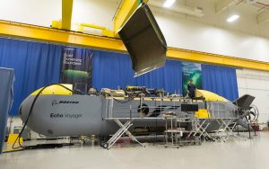
A typical XLUUV is shown in Figure 1.1 and is known at the Boeing Echo Voyager XLUUV. The Echo Voyager is 51 feet in length and has a rectangular cross section of 8.5 feet x 8.5 feet, a weight in air of 50 tons, and a range of 6,500 nautical miles. It can accommodate a modular payload section up to 34 feet in length and provides 2,000 cubic feet of internal payload volume.
Figure 1.1 Boeing Echo Voyager XLUUV. Courtesy of Boeing (https://www.boeing.com/defense/autonomous-systems/echo-voyager/index.page)
International Regulations
The regulatory authority that serves the international maritime community is known as the ‘International Maritime Organization’ and is an arm of the United Nations (UN). The UN has a secretariat of flag states where regulations and conventions are debated and agreed. The IMO provides rules that follow the regulations and are adopted across all territorial and international waters. There are a number of regulations that cover UUVs and are associated with the prevention of marine pollution (MARPOL), standards of training and certification (STCW) and safety conventions (SOLAS). MARPOL applies to the protection of the marine environment from the craft itself, STCW provides a competency framework for operators of UUVs and SOLAS applies to structural integrity of UUVs and other seafaring craft, manned or unmanned (American Bureau of Shipping, 2019). Emissions control under MARPOL Annex VI restricts the emissions of nitrogen (NOX) and sulfur (SOX) pollutants during the combustion of diesel in prime movers. However, restrictions in ozone, particulates and greenhouse gases are included in subsequent amendments of Annex VI.
The standards are arranged in three tiers I, II, and III. Tier I was established in 1997 and ratified in 2004, whereas Tiers II and III were established in 2008 and ratified in 2010. NOX limits apply globally, whereas SOX limits apply regionally. Large seafaring vessels typically produce relative CO2 emissions between 1 – 3, whereas airplanes emit 398 relative units of CO2, small goods vehicles emit 226 relative units of CO2, large articulated trucks emit 49 relative units of CO2, while railway wagons emit 6 relative units of CO2. Therefore, ships and submersibles have a low carbon footprint than other forms of global transport.
Fuels and Propulsion: Current Disruptive Technologies
Diesel Fuels
Diesel engines have improved significantly since the 1980s with advances associated with increased bore/stroke ratio, slow- and medium-speed engines, improved peak pressures and significant fuel reductions in two-stroke engines. Turbocharging efficiency and fuel injection technology have contributed to further reductions in consumption in four-stroke engines. However, since the mid-1990s, the design of diesel engines changed due to the reduction of NOX and SOX emissions without changing fuel efficiency requirements. Marine engine design has changed since the mid-1990s and include changes such as: low NOX combustions with adjustable camshafts, variable inlet valve controls, high boost pressures and better combustion chamber design, greater mechanical strength of engines, two-stage turbocharging, exhaust gas recirculation, waste gate technology, sequential turbocharging, variable turbine geometry, humidification of inlet air, use of selective catalytic reduction systems, exhaust gas scrubbing, and the emulsification of fuels (MAN Energy Solutions, 2018).
The disruptive technologies used for improving NOX emissions in diesel engines are focused on reducing peak temperatures and duration of the combustion cycle and the use of Miller cycle inlet valve timings and higher-pressure turbochargers. It has been discovered that using the Miller cycle instead of the Diesel cycle during combustion reduces NOX emissions by reducing the cycle temperature at constant high pressure, hence the use and further development of high-pressure turbocharging using two-stage turbochargers.
Biofuels
Collections of cells and proteins and the conditions under which these natural living systems grow and replicate created the first biofuels. The first generation of biofuels consisted of biodiesel and bioethanol. Biodiesel is manufactured from vegetable oils (coconut, palm, rape seed, soybean, and tallow) and animal fats. They are classed as fatty acid methyl esters (FAME) and are manufactured when vegetable oils and animal fats react with alcohol such as methanol. Bioethanol is manufactured by fermenting renewables based on sugar or starch. These ingredients are typically cassava, corn, sorghum, sugar beets, sugar cane and wheat. The variability in FAME stability in various conditions is due to the type of ingredients used in their formulation and their ability to absorb water and hold in suspension, which causes hydrolytic reactions that causes FAME to revert to fatty acids. If water is dissociated microbiological growth can clog filters and corrosion of engine parts can occur.
Disruptors that may enhance and increase the use of biofuels focus on producing synthetic fuels based on branch-chain higher alcohols, E-coli, microorganisms such as yeast and algae-based fuels. Other types of fuels that may be used in the future could be based on di-methyl ether (DME) that can be produced from biomass, natural coal and gas and oil residues. It is condensed when pressured above 0.5 MPa, is non-toxic and environmentally benign and is not dissimilar to liquid natural gas (LNG). It has a high cetane number and is high in oxygen content when mixed in air achieving smokeless combustion and very low formation of particulates. However, it has a lower density than other fuels and lower combustion enthalpy. It requires lubricity and corrosive inhibiting additives, but despite the issues of lubricity and corrosion, it has high thermal efficiency, low noise, low NOX emissions and is low in particulates (low soot formation) (MAN Energy Solutions, 2018).
Liquid Natural Gas (LNG) Fuels
The principal constituent of LNG is CH4, which reduces CO2 emissions by 25%. Also, NOX production is 85% less due to compression ratio and combustion temperature differences. Since sulfur is absent from the fuel, SOX emissions are non-existent. The advantages of using LNG are described as low emissions, existing marine engines burn LNG, LNG is cheaper than most fuels, and fueling technology is well established. The disadvantages associated with LNG are associated with methane slip and that LNG requires a heat source to evaporate it to form a gas used for combustion.
Gas Turbine Propulsion
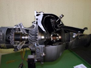
Gas turbines are used for direct propulsion or can be used to generate electricity to electric motors when not used for propulsion. Figure 1.2 shows a typical cross-section of a gas turbine. This allows them to be used for hybrid operations coupled to diesel engines or diesel generators. Gas turbines have the advantage of low weight compared to standard prime movers and aero-derivative turbines burn distillate fuels that satisfy current regulations on emissions and smoke generation. However, distillate fuels are more expensive than standard marine fuels, and are very powerful when turbines are heat recovery turbines are coupled to use the exhaust gases to increase thermal efficiency for electricity generation. Indeed, gas turbines can be used for propulsion and for providing electricity to secondary propulsion units. The advantages of using gas turbines lies in the fact that they are high power density prime movers and are low weight and small size. NOX emissions are low and SOX emissions are negligible due to use of high-grade fuels. However, distillate fuels are expensive, turbines are less efficient as ambient temperature increases and thermal efficiencies are lower compared to diesel engines (MAN Energy Solutions, 2018).
Figure 1.2 Cross section of a typical gas turbine engine. Courtesy of Tilyudai and reused under license CC BY-NC-SA 2.0. To view a copy of this license, visit https://creativecommons.org/licenses/by-nc-sa/2.0/.
Nuclear Propulsion
Energy generation and storage usually relies on breaking chemical bonds between atoms. Nuclear power relies on converting large and heavy nuclei into smaller fission products by controlled chain reactions. A large amount of heat is generated that is converted to usable power via an appropriate thermodynamic cycle. Nuclear propulsion is CO2 free and is quite disruptive in terms of using it as a propulsion source. Molten salt thorium reactors are considered to be disruptors to using diesel and turbine power units owing to the abundance of thorium compared to uranium and using molten salts of fluorides and chlorides to act as coolants operating at temperatures in the range of 650OC to 700 OC. Such reactors are in development and the use on seafaring craft is governed by the IMO’s Code of Safety for Nuclear Ships, Resolution A.491 (XII), 1981. However, they have not been used on UUVs and small submersibles so experience and knowledge of operation from larger submarines may have to be transferred to the naval architect responsible for using them in UUVs. The advantages of using them include no emissions generated, the design of reactors is well established so could easily be adapted for UUVs, they can be small and modular in design, the cost of fuel is paid at the beginning of use and is not subjected to price fluctuations. The disadvantages of this technology are associated with knowledge of safety and the lack of systems engineering knowledge in personnel that would prevent wider adoption, design of UUVs may be constrained because of the technology, regulatory standards would need to be created for use in UUVs, support systems and planned response to misuse would need to be developed and for use a new and controversial technology, proof of concept and the management of public perception will need to be managed (MAN Energy Solutions, 2018).
Battery Technology
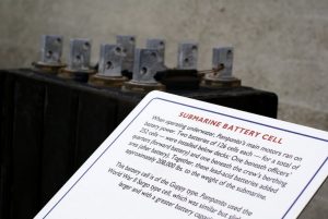
Battery technology is very well advanced and documented. New battery chemistries are fundamental and constitute the most disruptive technology associated with their wider use on UUVs. Metal-sulfur is typical, but metal-air is becoming more widespread such as lithium-air being the leading couple due to its ability to provide the highest amount of energy per density of metal. However, post lithium-air battery technology is being developed due to the limited supply of lithium. The use of magnesium-air batteries is being considered and the technology developed because magnesium can be harvested from salt water. However, energy storage is thought to be the key to the future for UUVs, so the development of supercapacitors to store charge is a key disruptor for many areas of transport, not least UUVs. The advantages of batteries on UUVs are focused on non-generation of emissions, continuous development means that they will get smaller and more powerful and that batteries can be used as hybrid power generators with combinations of other modes of propulsion (MAN Energy Solutions, 2018). Disadvantages include size and the fact that they need to be recharged/replaced when the UUV is being used in service. A submarine battery cell is shown in Figure 1.3.
Figure 1.3 Submarine battery cell. Courtesy of Jamie Sanford and used with permission under license CC BY-NC 2.0. To view a copy of this license, visit https://creativecommons.org/licenses/by-nc/2.0/.
Fuel Cells
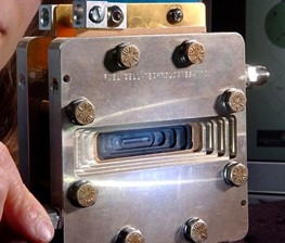
Fuel cells were invented in 1838 but not widely adopted until recently due to their low mass, the emission of the fuel cell is water, and because materials technology has advanced so much in recent years that fuel cells may be widely used. They are electro-chemical and require support plant such as pumps and fans and rely on hydrogen and oxygen combining to release energy. The reactants consumed by the fuel cell is stored externally rather than internally (batteries) and can be renewed continuously rather than depleted (battery). Therefore, it produces power all the time as long at the reactants are supplied to it. There are certain drawbacks to their use such as hydrogen supply issues at sea and they have lower specific power and density compared to diesel engines. They also provide direct current output that is not compatible with coupling to mechanical transmission systems (MAN Energy Solutions, 2018). However, they can be used for auxiliary power sources, methanol can be used as a substitute fuel, they are quiet (no moving parts), and they require clean fuels that do not emit SOX or NOX due to low temperature operation. Figure 1.4 shows a fuel cell developed by the Argonne National Laboratory, USA.
Figure 1.4 Fuel cell. Courtesy of Argonne National Laboratory (license CC BY-NC-SA 2.0). To view a copy of this license, visit https://creativecommons.org/licenses/by-nc-sa/2.0/.
Hydrogen Fuel
Hydrogen is a potential disruptive fuel for use on UUVs and can come from sources such as wind, hydro-electric, nuclear or as a conventional fuel used in fuel cells. The advantages of using liquid hydrogen are that it does not produce CO2 or SOX emissions, it uses land-based sources of power for creation, it can be used in fuel cells and in internal combustion engines and burning it produces a large amount of fresh water (MAN Energy Solutions, 2018). However, it is unknown in the marine sector, has some safety issues and a supply infrastructure would be needed for use in UUVs.
Future Disruptive Technologies for Propulsion and Fuels
Hybrid Propulsion
Hybrid propulsion is an option where different modes of power can be used to optimize the operation of the UUV. The reasons for selecting hybrid propulsion systems are focused on reduced fuel consumption, reduced impact of CO2 and other pollutants, variable future fuel costs and supply, insurance against increasing environmental legislation, noise reduction, operating in zero emission mode, and lower amount of maintenance.
Further disruptive technologies associated with propulsion include the use of propellers such as fixed pitch, controllable pitch propellers and ducted propellers. The type of propeller used for UUVs is determined by operational conditions. Typically, for small high-speed UUVs both rotational speed and propeller advance can be high and it can be difficult to control the effects of cavitation. Therefore, developments in the use of ducted and podded propellers will need to be made to apply this disruptive technology to UUVs. Other types of propeller to be considered for use on UUVs include contra-rotating propellers, and cycloidal propellers. The naval architect should maximize the diameter of the propeller so that torque, thrust, and propeller efficiency are maximized. The propeller can be approximated to a Wageningen B-screw series using open water design data. This is well characterized in most texts concerned with naval architecture (Lewis, 1988). Other disruptive technologies to consider for propulsion is waterjet propulsion and magneto hydrodynamic propulsion for small UUVs.
Energy Saving Devices
Energy saving devices associated with hydrodynamic flow are considered in three sections of the hull: before the propeller, at the propeller and after the propeller. There are some overlapping areas but mostly operate at the boundary layer and in the wake of the UUV. Devices placed on the flow of the propeller include wake equalizing ducts, asymmetric stern, Grothuis spoilers, partial stern tunnels, Mewis ducts, reaction fins, Zozen nozzles, and integrated ducted propellers.
Disruptive technologies applied to the propeller area include low speed propellers, propellers with end plates, Kappel propellers and propeller boss cap fins. For energy saving behind the propeller, grim vane wheels, rudder thrusting fins and rubber bulb fins are adopted depending on the mode of operation (Hughes, 2010).
Hull Design (Appendages and Coatings)
The efficiency of the hull is governed by the form of the hull and its dimensions (Nicholls, 2020). The hull envelope for submersibles is described by the Jackson hull-form (Figure 1.5) (Hughes, 2010). However, the stern of the UUV can be improved by using the Myring hull-form with its axisymmetric geometry. The Myring hull-form is a function of five variables: forward length of hull-section (Lfwd), parallel mid-body length (Lmid), forward curvature index (n), tail semi-angle (α), and maximum hull-form diameter (D).
The length of the aft hull-section (Laft) is (Eq. 1.1):
(1.1)
Laft = 100 – ( Lfwd + Lmid )
The radius of the forward hull-section, Rfwd, for a given axial coordinate, x, is defined as a modified semi-ellipsoid (Eq. 1.2):
(1.2)
Rfwd = (D /2) { [ 1 – ( x- Lfwd / x ) 2 ] n }
The radius of the aft hull-section, Raft, is defined as (Eq. 1.3):
(1.3)
Raft = (D /2) – { [ (3D/2Laft 2 – tan α / Laft) ( x – Lfwd – Laft ) 2 ] }
FORWARD-BODY MID-BODY AFT-BODY
Figure 1.5 Jackson hull-form geometry. [Adapted from Open Clipart Vectors by pixabay (Public Domain Image)]
The Myring hull-form is similar to the Jackson hull-form. However, the semi-angle of the aft section provides the naval architect with the ability to account for stern flows effects due to the geometry of the hull-section. The use of coatings on the Myring hull-form has yet to be investigated as a potential disruptive technology that could changes the characteristics of skin friction resistance and reduced biofouling.
Hull coatings and roughness is significant when considering the motion of UUVs. Hull coatings minimize the skin friction component of resistance and prevent fouling of the surface. Tin-based coatings have been used regularly in marine applications to prevent fouling but are detrimental to the environment. Therefore, disruptive technologies are focused on providing environmentally-friendly coatings such as electrochemically active coatings that allow the injection of boundary interfaces with bubbles so that an air cushion can be activated under certain conditions to reduce friction and disrupt the fouling process. Investigations into the texture of coating/hull surfaces will need to be conducted to emulate the skin of marine mammals so that friction and fouling is minimized or eliminated completely.
Superconducting Electric Motors
Electric motors are very efficient, but superconducting electric motors are highly efficient (~ 99%). This allows them to reduce operating costs of UUVs and reduce emissions. Superconducting motors are smaller in size, typically developing power per weight in the region of 30 kW/kg compared to standard electric motors ~ 5 kW/kg. High temperature superconductors discovered in 1986 are useful for developing this technology, but the discovery of magnesium diboride as a superconducting material in 2001 means that its lower critical temperature and sensitivity to magnetic fields will need to be adapted for use in rotating electrical machinery. The potential advantages of this disruptive technology include very low losses in electrical machines such as motors and the size and weight of the motor compared to traditional electric motors is much lower. However, the technology is yet to be proven at sea.
Conclusions: Naval Architect’s Role
The role of the naval architect is becoming increasingly complex and broad especially when one considers the effects of extreme weather and the minimization of using the earth’s scarce resources (Lewis, 1988). The future naval architect will need to work with natural scientists, such as marine biologists, in order to design vessels that work with nature to minimize the impact on the natural world (Hughes, 2010). The role will continue to work with engineers from other disciplines, project managers and business administrators and we may see the development of new academic courses that blend the principles of naval architecture with business studies that includes the commercial aspects of UUVs such as ‘naval systems architecture’ or ‘marine systems engineering’ (MAN Energy Solutions, 2018). The UUV must be considered as a system in order to design an environmentally beneficial craft. This means that the design, operation, and maintenance of the UUV is an integrated system, and that the naval architect needs to fully understand the operational and engineering principles that form the systems architecture of UUVs. The potential integration of disruptive technologies into the design of UUVs provides opportunities to further advance the field of underwater systems especially in the current political and economic climate.
Questions
- What are the drivers for change in terms of using new fuels for propulsion units in UUVs?
- Name and explain the key international regulations that support the design and operation of submersibles and other forms of UUVs.
- Describe the disruptive technology driving the development of diesel engines and explain why the Miller thermodynamic cycle better than the Diesel cycle in the context of disruptive technologies applied to diesel engines?
- Discuss and describe the current disruptive technologies that affect the design, maintenance, and operations of UUVs.
- The choice of fuel is dependent on the type of prime mover used in a UUV. What are the environmental benefits of using biofuels, LNG, and hydrogen?
- What is hybrid propulsion? Name its advantages and disadvantages.
- Comment on the design a the UUV’s hull section and the naval architect’s role in designing UUVs subjected to future disruptive technologies.
- What are the advantages and disadvantages of using superconducting electric motors in UUVs?
References
American Bureau of Shipping. (2019). ABS Rules for Building and Classifying Underwater Vehicles, Systems and Hyperbaric Facilities. Houston, Texas: American Bureau of Shipping.
Button, R. W. (2009). A Survey of Missions for Unmanned Undersea Vehicles. Santa Monica, California, USA: RAND Corporation.
Department of Defense. (2011). Unmanned Systems Integration Roadmap: 2011 – 2036. Washington DC, USA: US Government.
Department of Defense. (2012). Sustaining US Global Leadership: Priorities for the 21st Century Defense. Washington DC, USA: US Government.
Department of the Navy. (2004). The Nay Unmanned Undersea Vehicle Master Plan. Washington DC, USA: US Government.
Hughes, O. F. (2010). Ship Structural Analysis and Design. New York, USA: Society of Naval Architects and Marine Engineers.
Lewis, E. V. (1988). Principles of Naval Architecture: Volumes I, II and III. New York, USA: Society of Naval Architects and Marine Engineers.
MAN Energy Solutions. (2018). Basics of Ship Propulsion. Berlin, Germany: MAN.
Nichols, R. K. (2020). Unmanned Vehicle Systems and Operation on Air, Sea and Land (Vol. IV). Manhattan: New Prairie Press.
US_Congress. (2020). Navy Large Unmanned Surface and Undersea Vehicles: Background and Issues for Congress (Report 45757). Washington DC: US Congress.
