4 UUVs, Advanced Sensors, Munitions Detection & USVs [Nichols]
Student Learning Objectives
- – To take a birds-eye view of UUVs in service of detecting, assessing, and classifying underwater munitions
- – To study the type of sensors and their performance objectives in underwater service
- – To focus on a specific UNCLASSIFIED NSWC PCD demonstration of three UUVs used for detection of munitions targets (both proud and buried)
- – To look at improvements in survey UUVs / on surface UVs for shallow water studies.
- – To see the future of this technology as a Black Swan event.[1]
What is the Advanced Weapons Problem that UUVs can solve?
There are underwater munitions sites around the world where the quantity and the type of munitions are either unknown or not well documented. These sites are unsafe and can’t be used for any other purpose. The sites need to be surveyed and all the munitions identified and if necessary disarmed. (Leasko, 2014). Underwater munitions falls in the murky purview (CLASSIFIED) of the National Unmanned Systems Shared Resource Center (NUSSRC) located at the Naval Surface Warfare Center Panama City Division (NSWC PCD). It has multiple offices associated with the Office of Naval Research (ONR) Mine Countermeasure (MCM) UUV systems integrated with advanced sonar, magnetic and electro-optical sensors.[2] These systems provide capability for experimentation and demonstration of current Science and Technology (S&T) and Research and Development (R&D) program assets as they apply to the detection and classification of underwater mines to be used for detection, assessment, and characterization of underwater munitions. (Leasko, 2014)
NSWC PCD
The Naval Surface Warfare Center Panama City Division (NSWC PCD) is one of many naval installations conducting S&T research around the world. NSWC PCD is a particularly fascinating one and has a huge mission. NSWC PCD Our mission is to conduct research, development, test, and evaluation (RDT&E) and in-service support of the following core mission areas: Mine Warfare Systems, Naval Special Warfare Systems, Diving and Life Support Systems, Amphibious/Expeditionary Maneuver Warfare Systems and other missions that occur in the littoral, or coastal, regions. NSWC PCD’s Technical Capabilities include: Air Cushion Vehicle Systems; Expeditionary Maneuver Warfare Systems Engineering and Integration; Special Warfare Maritime Mobility Mission Systems and Mission Support equipment; Mine Countermeasure Detect and Engage Systems; Modular Mission Packaging; Platform Integration and Handling; Littoral Mission Systems integration and Modular Mission Packages Certification; Unmanned Systems Engineering and Integration; Autonomous Diving and Diving Support Systems; and Surface Life Support Systems for Extreme Environments. Their major facilities include: Diving and Life Support Complex; Mine Warfare Complex; Special Warfare Research and Engineering Complex; Expeditionary Warfare Complex; Landing Craft Air Cushion (LCAC) Facility; LCAC Software Integration Laboratory; Human Systems Integration Usability Lab; USMC Amphibious Raids and Reconnaissance; Integration Facility; Coastal Test Range; Prototype Fabrication Facility; Additive Manufacturing or 3D printing for rapid prototyping; and 3D Expeditionary Laser Scanning. This is the purview of just one of the ten plus NSCW warfare centers. These are all part of the Naval Sea Systems Command (NSSC), “The force behind the fleet.” (NSWC, 2020)
Murky Waters
We can get a OPEN SOURCE peek into the use of NAVSEA’s MCM UUV assets to evaluate and demonstrate current technologies with advanced detection, assessment, and characterization sensor packages. NSWC PCD published a report (UNCLASSIFIED) on their Post Mission Analysis (PMA) of all sensor data relating to the performance of UUV technologies for the underwater munitions problem so identified. (Leasko, 2014) [3]
The PMA data collection / demonstration by NSWC PCD occurred in early 2011.
Technology
Three specific UUV assets in the NUSSRC inventory[4] that can address the detection and characterization of underwater munitions in an organic fashion are the Remote Environmental Measuring Units 100 (REMUS 100); the Blufin12 Buried Mine Identification (BMI) UUV systems and the REMUS 600 BMI UUV, with a separate magnetic sensor, the Real-time Tracking Laser Scalar Gradiometer (LSG) to collect data over the field too. (Leasko, 2014)
REMUS Group
REMUS makes four serious UUV products. REMUS 100, REMUS 300, REMUS 600 and the REMUS 6000. Figure 4.1 shows the REMUS 100/MK 18 Mod 1. The first two UUVs are described.
Source: (REMUS, 2020)
The REMUS 100 is a man-portable Unmanned Underwater Vehicle (UUV) designed for rapid deployment, it can be easily transported via helicopter and launched from a dock or any vessel of opportunity. With a maximum operating depth of 100 meters and a mission duration of up to 12 hours, it is ideal for rapid, low-logistics deployments. (REMUS, 2020). The UUV is 67” L x 7.5” D and weighs 80 lbs. It has a maximum depth of 328 ft and 6 hours operations time. It is equipped with the following: (REMUS -1., 2020)
Environmental Sensor
– Fluorometer/Backscatter Sensor
– Fast Response Conductivity
Temperature Sensor
– Oxygen Optode
– Turbidity Sensor
Imaging Hardware
– Bathymetric Side Scan Sonar
– Video Camera Recorder (VCR) Module
– Lightbar for VCR Module
– Gap-Filler Sonar
Communication/Navigation Equipment
– Precision GPS
– Military GPS
– Wi-Fi Communications
– Iridium Communications
– NavP Inertial Navigation System
with Payload Processor
Software
– Navlab Post Processing Software
– RECON Software
– Reflection Post-Mission Analysis Software
Figure 4.1 REMUS 100/MK 18 Mod 1
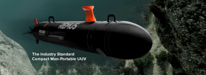
Source: (REMUS -1., 2020)
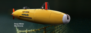
REMUS 600
The REMUS 600 is a midsized UUV designed for easy transport and maximum versatility, the REMUS 600 (the US Navy MK18 Mod 2 and LBS AUV Program vehicles) is a highly configurable vehicle with a maximum operating depth of 600 meters. Able to be deployed from vessels as small as an 11 meter RHIB and boasting a maximum mission duration of 24 hours, the REMUS 600 can be outfitted with a broad range of sensors to meet the requirements of nearly any mission. (REMUS -2., 2020) The REMUS 600 has the following specifications: Vehicle Diameter 12.75 in; diameter varies depending upon module (for 600 m depth configuration); Vehicle Length Min length ~9 ft to Max length ~18 ft; length varies depending upon module configuration; Max Weight in Air Min ~850 lbs where weight varies depending upon module configuration; Maximum Operating Depth 600 meters (1500 meter configuration available);Energy 5.4 kWh rechargeable Li-ion battery; (Second 5.4 kWh battery tray is optional), exchangeable battery option available; and Endurance Typical mission endurance is up to 24 hours in standard configuration; subject to speed, battery and sensor configurations. (REMUS -3., 2020) It is equipped with the following (See Figure 4.2) :
Standard System Configurations
– Doppler Velocity Log (DVL)
– Compass or Inertial Navigation System as
Standard Depending on Configuration
– Acoustic Modem (Low & High Frequency Options Available)
– Pressure Depth Sensor
– Conductivity & Temperature Sensor
– GPS/Wi-Fi/Iridium
– Emergency Recovery Equipment
– Terrain Avoidance Sonar
Optional Equipment
– Up to (2) Battery Trays
– Responder for Surface Ultra Short Baseline (USBL)
– Navigation Aiding
– NavP/HG 9900 INS with Payload Processor
– Obstacle Avoidance Sonar
Optional Sensors
– Dual Frequency Sidescan Sonar
– HiSAS 2040 Synthetic Aperture Sonar
– Dynamically Focused Sidescan Sonar
– Optical Environmental Characterization Sensors
– Video Camera
– Multi-Beam Echo Sounder (MBES)
– Electronic Still Camera (ESC)
– Sub-Bottom Profiler (SBP)
– Fish Finding Echo Sounders
– Oxygen Sensors
– Photosynthetically Active Radiation (PAR) Sensor
– LED Based Lights & Strobes for Cameras
– High Precision, Dual-Band GPS Receiver
– Terrain Avoidance Sonar (Obstacle Avoidance Sonar optional)
– Other Custom Sensor Options Available
Shipboard Devices
– Shipboard Communications Mast
– Power Box with Battery Charger/Conditioner
– Shipboard Communications System
(GPS, Iridium, Wi-Fi and Optional Freewave)
– Acoustic Communications Bottle
– Ranger Deck Box
– Acoustic Transducer Towfish
– Releasable Acoustic Transponders
– Portable Surface Communications Station
Figure 4.2 REMUS 600 UUV
“The REMUS 6000 AUV (Figure 4.3) was designed under a cooperative program involving the Naval Oceanographic Office, the Office of Naval Research and the Woods Hole Oceanographic Institution (WHOI) in support of deep-water autonomous operations. The REMUS 6000 AUV boasts the same proven software and electronic subsystems found in our highly successful REMUS 100 AUV, with a depth rating, endurance, and payload that allow for autonomous operations in up to 6000 meters of water.” (REMUS -4, 2020) The REMUS 6000 has Vehicle Diameter 28 in by Vehicle Length 13 ft and weighs in Air 1900 lbs; works at Maximum Operating Depth 6000 meters (4000 meter configuration also available); Energy 12 kWh rechargeable Li-ion battery pack for two pressure housings; a second 12 kWh set can be purchased as an option with system permitting 2-hour turn around; charge time is typically 8 hours and the batteries are rechargeable up to 300 cycles or for 5 years under recommended storage conditions; and has Endurance Typical mission duration of 22 hours; subject to speed & sensor configuration. (REMUS -5., 2020) What makes the REMUS 6000 is “technical horsepower:”
Standard System Configurations
– Acoustic Doppler Current Profiler/Doppler
Velocity Log (ADCP/DVL)
– Acoustic Modem (Low Frequency)
– Inertial Navigation System (INS)
– Sidescan Sonar
– Depth Sensor
– Conductivity & Temperature Sensor
– GPS/Wi-Fi/Iridium
Optional Sensors
– Dual Frequency Sidescan Sonar
– ECO Sensors
– Multi-Beam Echo Sounder (MBES)
– Video Camera
– Electronic Still Camera (ESC) with
200 Watt-Sec Strobe Lighting
– Sub-Bottom Profiler (SBP)
– NavP/HG 9900 INS with Payload Processor
Deployment Options
– Launch & Recovery System
– Operations Van
– Side Launch Rotation Table
Shipboard Devices
– Shipboard Communications Console
– Power Box with Battery Charger
– Antenna Box
(GPS, Iridium, Wi-Fi and Optional Freewave)
– Acoustic Communications Bottle
– Ranger Deck Box
– Towfish
– Acoustic Transponders
– HiPAP USBL Capability
Vehicle Interface Program (VIP)
The REMUS 6000 uses essentially the same Vehicle Interface Program (VIP) as the proven REMUS 100 AUV. This highly intuitive VIP greatly simplifies vehicle maintenance, mission planning, vehicle checkout, and data analysis; and will run on any PC or laptop operating under Windows.® Communication between the vehicle and the host is conducted via a standard Ethernet connection. Among other features, the VIP includes:
– An integrated text editor for construction of the mission file.
– A map view that illustrates the planned mission for review.
– Automatic error checking performed on all aspects of the planned
mission, with warning messages that appear if any mission
parameters are incorrect.
– A set of quick-look indicators display system status, where green
indicates OK, and red indicates a fault.
Figure 4.3 REMUS 6000
Source: (REMUS -5., 2020)
Bluefin 12 Buried Mine Identification (BMI) UUV System
In a paper by (G. Sulzberger, 2009) the Bluefin 12 BMI was abstracted as follows: “The Bluefin12 Buried Mine Identification (BMI) System is used as the platform to develop a capability for the identification of buried mines. This system houses the bottom looking sonar, the Real-time Tracking Gradiometer (RTG), and an Electro-Optic Imager (EOI).
The objective for the RTG is the enhancement of the processing that extracts target locations and magnetic moments from the raw RTG data. (G. Sulzberger, 2009) added the capability to conduct real-time processing capability to provide autonomous target classification and localization results soon after the UUV passes the target, while the system is still performing the mission. These results will be shared with the vehicle or other sensors for transmission back to a base station when the vehicle surfaces. The objectives for the EOI include additions to the control software and the development of a set of versatile image processing techniques. A significant goal is to develop the ability to make images viewable remotely over the vehicle’s RF link. This allows for a quick review of contacts and improved flexibility in mission planning and execution. Image processing goals included the development of image enhancement algorithms that could be applied to all EOI data. The intent of the enhancement algorithms is to enhance image contrast and sharpness to better differentiate targets from background and increase target detail. The software will be used to batch process large amounts of raw EOI images and save them in a format so that the user can scroll through the images using a standard image viewer.” (G. Sulzberger, 2009) (Figure 4.4)
Figure 4.4 Bluefin12 BMI
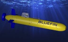
Source: (Bluefin Robotics, 2020)
Demonstration
The objective of the NSWC PCD MR-201103 project conducted in 2011 was to leverage the Office of Naval Research’s (ONR) Mine Countermeasures (MCM) unmanned underwater vehicle (UUV) assets to evaluate and demonstrate the applicability of existing ONR MCM UUV technologies integrated with advanced sensor packages for facilitating detection, assessment, and characterization of underwater munitions.
Figure 4.5 Bluefin 12 Internals
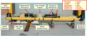
Source: (Bernstein, 29 June 2012)
A number of sensors were employed in the demonstration. The BMI sensor suite consists of the Buried Object Scanning Sonar (BOSS) and the Realtime Tracking Gradiometer (RTG) fitted to the Bluefin-12 UUV. The REMUS100 system carries a dual frequency, 900/1800 kHz side scan sonar. (Figure 4.5) The REMUS system provided high resolution acoustic images of proud objects, while the BMI sensor suite on the Bluefin-12 UUV provided acoustic images of buried objects and the magnetic moments of targets or clusters within range of the RTG sensor. The combination of the data from both UUV systems was designed to enable detection of acoustically reflective targets and discrimination between proud and buried state, provide size and aspect information, and indicate which contain magnetic material of the level seen for munitions. (SERDP-ESTCP, 2012)
Demonstration Results
Quoting from the (SERDP-ESTCP, 2012) report, the Results were not without Implementation errors.
“A small underwater munitions test site was planted in the Davis Point area of St. Andrew Bay near Naval Surface Warfare Center-Panama City Division (NSWC PCD). Five nominal 100-m-long target lines spaced 2 m apart were laid parallel to each other. The first two lines had individual targets spaced along the lines and aligned at random orientations relative to the target lines. One line had the targets proud and the other line had the targets flush buried. The third through fifth lines had two clusters of targets on each line. Lines one and two provided baseline measurement data for each individual target type. Lines three through five provided acoustic and magnetic data for clusters of munitions in different states of burial and orientation. The planted locations of the targets were determined by their drop locations from the surface vessel using plumb lines and a GPS system.
The BOSS sensor clearly demonstrated the capability of detecting and imaging unexploded ordnance (UXO) targets of the class M targets in proud, partially buried, and fully buried configurations. Discriminating between the different targets was accomplished by comparing the known target physical dimensions with the measured dimensions extracted from the BOSS imagery. However, discriminating multiple targets in a clustered configuration was difficult for the case of targets closely spaced together (target 16-CL1-M). This is due to the medium resolution of the BOSS sensor. The developer of the BOSS system has recommended increasing the transmit frequency to increase the resolution to enhance the imagery but funding for this effort has not been forthcoming.
The RTG experienced hardware failure during the data collection event at the end of June, leading to lost data. A likely candidate for this failure is the oil-filled cables that connect the sensor head to the electronics bottle. These cables and their connection points have failed in the past with similar effects on the data. A refurbishment and recalibration of the RTG system would be beneficial for future testing events and will be necessary to improve results.” (SERDP-ESTCP, 2012)
Implementation Issues
The technologies encountered numerous problems during their deployment, including the failure of multiple channels in each sensor, not allowing much of the data to be recovered. The sensor suite used in the experiment was unique research and development equipment developed by the Navy for finding buried mines. As such, it cannot be procured commercially. Additional equipment would have to be custom-built.
Improvements in magnetic sensors have been made since the RTG sensor was constructed, and alternate sensor designs might be considered, including the LSG sensor. Collaboration between government and contractor subject matter experts would be required to develop a state-of-the-art gradiometer suitable for integration with the Bluefin-12 UUV and the BOSS sensor for regular use in munitions surveying. As a part of that effort, software for processing gradiometer and BOSS data would be streamlined to enable survey contractors to use the system with minimal additional training. (SERDP-ESTCP, 2012)
Success Criteria and Performance Objectives
Before we describe a selected sensors and findings, it is useful to know what the success criteria was for this demonstration. First we need to think in terms of Performance Objectives.
Performance Objectives (PO) Remote Environmental Measuring Units REMUS 100.
The performance objective (PO) for the REMUS 100 was to first provide a wide area search over the entire site areas with the 900 kHz side scan sonar. Once the wide area search was complete the sonar imagery from that search would provide information on the overall assessment of proud objects in the area and if any are contacts of interest. A follow-on lower altitude, small-area detailed survey and target reacquisition of the contact of interest would be performed operating the sonar at 1800 kHz. The 1800 kHz frequency provided with picture quality sonar imagery that enhances classification and identification of the proud contacts of interest. Along with sonar data camera imagery it would provide clear picture quality imageries of the contact of interest.
This PO was not accomplished because the REMUS camera was unavailable. The survey was performed on a clear water day with the EO sensors on board the REMUS 600.
Performance Objectives – Buried Object Scanning Sonar (BOSS)
Table 4.1 summarizes the BOSS system POs. The objectives include assessment of the probability of detection, the degree of burial, size, shape, and orientation determined and localization accuracy against a combination of small and large UXO targets. (Leasko, 2014) The planned tests were not blind tests. They were designed to determine the sidescan, BOSS and RTG combined capabilities against proud (clearly visable and not buried) and buried targets and to determine whether further optimization of the multi sensor approach, and further performance testing was warranted.
The PO was to demonstrate and measure the ability to classify all contacts using: 1) the BOSS to measure target size, shape, and orientation, 2) the RTG sensor to determine which BOSS contacts are ferrous and non-ferrous and to measure the magnetic moment of the ferrous contacts and 3) compare BOSS with REMUS sidescan data to indicate which contacts are buried and which are proud and to enhance localization of those contacts. (Leasko, 2014)
Table 4.1 Performance Objectives for the BOSS Sensors
| Performance Objective | Metric | Data Required | Success Criteria |
| Quantitative Performance Objectives | |||
| Detection of all munitions of interest | Percent detected of seeded items | Location of seeded Items[5] | Pd=0.90 [6] |
| Determine the degree of burial, size, shape, and orientation of contacts. | Percent correct classification of the burial depth, size, shape, and orientation of the seeded targets. | Validation data for selected targets | Demonstration of >90% correct classification of the size, shape, and orientation of the targets. Length and burial measurements considered correct shall be within 25% of actual |
| Location accuracy | Average localization error in meters from latitude and longitude ground truth localization for seed items | Location of seed items surveyed to accuracy of 1.0m | ΔLocalization Error < 1m from ground truth |
| Qualitative Performance Objectives | |||
| Ease of Use | Feedback from technician on usability of technology and time required |
Source: (Leasko, 2014)
Performance Objectives – Real-Time Tracking Gradiometer (RTG) / Laser Scalar Gradiometer (LSG)
The performance objectives for the RTG system are summarized in Table 4.2. The objectives include a demonstration of the performance of detection, the ability to measure the magnetic moment and be able to localize the contacts or clusters of targets.
Table 4.2 Performance Objectives for the RTG Sensors
| Performance Objective | Metric | Data Required | Success Criteria | ||
| Quantitative Performance Objectives | |||||
| Detection of all ferrous munitions of interest | Percent detected of seeded ferrous items | Location of seeded Items | Pd=0.90 | ||
| Measurement of ferrous target magnetic moment | For individual planted targets, the percent of targets whose magnetic moment is measured during a flyover to within 20% of that measured in the laboratory, for the particular altitude flown.[7] | Validation data for selected targets [8] |
|
||
| Location accuracy [9] | Average localization error in meters from latitude and longitude ground truth localization for seed items | Location of seed items surveyed to accuracy of 1.0m[10] | ΔLocalization Error < 1m from ground truth | ||
| Qualitative Performance Objectives | |||||
| Ease of Use | Feedback from technician on usability of technology and time required |
Performance Assessments
Remote Environmental Measuring Units 100 (REMUS 100)
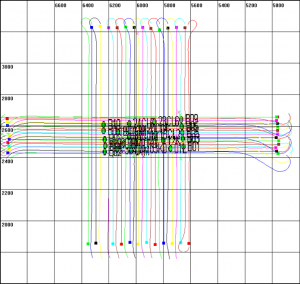
Figure 4.6 shows the REMUS 100 UUV mission over the test field. The mission was a combine 900 kHz and 1800 kHz sonar surveys. The blue lines with arrows, represents the track lines and vehicle direction as it traveled though the test field surveying at 900 kHz. The purple lines with arrows, represents the track lines and vehicle direction as it traveled though the test field surveying at 1800 kHz. The green (+) symbol represents the locations of the targets detected. Sonar imagery of this is displayed in Figures 14 – 26. The red (+) symbol represents the location of a detected UXO target out of place from Cluster 16-CL1_M. It is thought that the UXO target was moved by a shrimper’s nets as they went through the test field.
Figure 4.6 REMUS 100 mission map
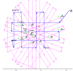
Source: (SERDP-ESTCP, 2012)
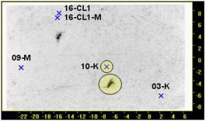
Figure 4.7 shows a sample RTG 1800 kHz sonar imagery of seeded point 04-M on Figure 4.6.
Figure 4.7 shows a sample RTG 1800 kHz sonar imagery of seeded point 04-M on Figure 4.6
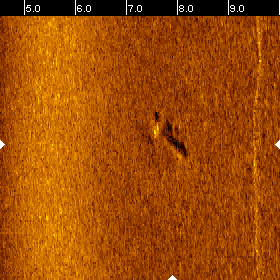
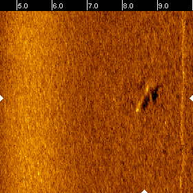
Source: (SERDP-ESTCP, 2012)
Figure 4.8 shows the interesting navigation tracks for the survey missions performed on 25 June 2011. Note the search patterns are designed to pick up proud and buried targets from 90 degree approaches.
Figure 4.8 Navigation tracks for the survey missions performed on 25 June 2011.
Source: (SERDP-ESTCP, 2012)
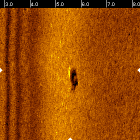
BOSS Images
The BOSS images consist of the X-Y plan view showing the plumbed position of the target represented by an “X” and the image of the target of interest highlighted with a circle and labeled with the target’s designation. A zoomed, 3D multi-aspect BOSS image for each target is also provides the X-Z and Y-Z perspective views to show target burial state. BOSS target localization, distance from BOSS localization to diver plumbed positions (“X”), target dimensions and burial state information for each of the targets is provided from BOSS PMA.[11]
Note that all BOSS-generated images in this report are for cases with sub-critical grazing angles in the sand bottom field. (SERDP-ESTCP, 2012)
Figure 4.9 shows BOSS imagery for target 10-K: (a) plan view image and (b) zoom image of target 10-K. Vertical axes are cross track, and horizontal axes are along track, in meters.
Figure 4.9 Example of BOSS imagery
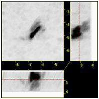
Source: (SERDP-ESTCP, 2012)
Summary – BOSS
According to Leasko (Leasko, 2014), the BOSS sensor clearly demonstrated the capability of detecting and imaging unexploded ordinance (UXO) targets of the class M targets in proud, partially buried and fully buried configurations. Discriminating between the different targets was accomplished by comparing the known target physical dimensions with the measured dimensions extracted from the BOSS imagery. However, discriminating multiple targets in a clustered configuration was difficult for the case of targets closely spaced together (target 16-CL1-M). This is due to the medium resolution of the BOSS sensor.
As to target localization, the BOSS system receives and uses UUV navigation information to calculate target localization. The present navigation package in the Bluefin12 UUV can be updated to improve its accuracy. The present method of obtaining the ground truth of targets deployed underwater can introduce errors especially in deeper water making it difficult to accurately assess target localization. (Leasko, 2014)
Modern mine warfare challenges today
What is the scope of the problem? The (Bernstein, 29 June 2012) demonstration referred to in this chapter constitutes a relatively small number of UXO targets to be detected, assessed and classified.
Mine warfare remains the most cost-effective of asymmetrical naval warfare. Mines are relatively cheap and being small allows them to be easily deployed. Indeed, with some kinds of mines, trucks and rafts will suffice. At present there are more than 300 different mines available. Some 50 countries currently have mining ability. The number of naval mine producing countries has increased by 75% since 1988. It is also noted that these mines are of an increasing sophistication while even the older type mines present a significant problem. It has been noted that mine warfare may become an issue with terrorist organizations. Mining busy shipping straits and mining shipping harbors remain some of the most serious threats. (Ocean Studies Board, 2012)
Clearing mines is an inexact science
Between 600,000 and 1,000,000 naval mines of all types were laid in WWII. Advancing military forces worked to clear mines from newly-taken areas, but extensive minefields remained in place after the war. Air-dropped mines had an additional problem for mine sweeping operations: they were not meticulously charted. In Japan, much of the B-29 mine-laying work had been performed at high altitude, with the drifting on the wind of mines carried by parachute adding a randomizing factor to their placement. Generalized danger areas were identified, with only the quantity of mines given in detail. Many WWII era still exist today. Mines aren’t the only UXO in the sea or close to land. Bomb fragments or UXO can still be found in Germany and England. More recently, Iraq and Afghanistan has a proliferation and specialization of IEDs. The exact number isn’t known but the injuries to US soldiers and indigence children / population is dramatic. For a lightly technically salted discussion of the types of mines, deployment history, and countermeasures see Naval Mines in Wikipedia. (Naval Mines, 2020)
Innovation seems to be the name of the game in UUV / USV Surveying
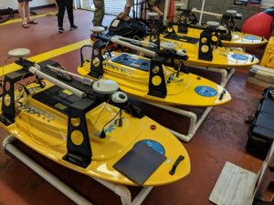
Shallow water has always been a captain’s concern and bottom conditions may obscure objects that are sonar resistant. Teledynemarine Oceanscience has produced a couple of interesting unmanned surface vehicles [boats] (USVs) for shallow water use, the 1250 and Boat 1800T – Trimble Edition. Teledynemarine Oceanscience Q-Boats® perform reliable remotely-controlled acoustic Doppler current profiling in streams, rivers, lakes and coastal waters all over the world. They reduce survey time, keep people safe during difficult conditions, and can access hard to reach locations. (Teledynemarine, 2020) See Figures 4.10 and 4.11
The Teledynemarine 1800-T Trimble edition has some key features:
- – Precise Trimble GNSS positioning and guidance
- – Real-time 2D survey for inspection and identification of obstructions
- – Cost effective method for ad hoc surveys
- – Increased safety and reduced cost: replaces dangerous diver inspection and expensive survey boat time. (Teledynemarine-1, 2020) [12]
Figure 4.10 Q-Boat 1250 designed specifically for shallow water applications
1250 Field shot
Source: (Teledynemarine, 2020)
Figure 4.11 Q-Boat 1800-T Trimble Ed.
Source: (Teledynemarine-1, 2020)
Conclusions: Why do the authors consider UUVs and USVs Disruptive Technologies of the future?
Several reasons.
Consider two interesting Black Swan events of the past and how the technology exponentially grew out of small seeds.
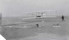
The date is December 17, 1903.
The Wright Flyer was the first successful heavier-than-air powered aircraft. Designed and built by the Wright brothers, they flew it four times on December 17, 1903, near Kill Devil Hills, about four miles south of Kitty Hawk, North Carolina. (Figure 4.12)
Figure 4.12 Wright brothers first flight photo
Source: (Crouch, 2014)
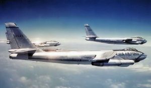
Results: Airline Industry, USAF, Space Command, FAA, Passenger and Freight Travel all over the world, bad airline snacks, unhappy TSA employees, Space Command. To prove the point see Figure 4.13:
17 Dec 1947–A mere 44 years to the day that the Wright brothers took to the air for the first powered flight of 12 seconds and traveled 120 feet at Kitty Hawk, NC, the Boeing B-47 Stratojet strategic bomber takes to the air for the first time. The Boeing B-47 Stratojet was a long range, six-engine, jet-powered strategic bomber designed to fly at high subsonic speed and at high altitude to avoid enemy interception. The B-47’s primary mission was to drop nuclear bombs on the Soviet Union. With its engines carried in nacelles under the swept wing, the B-47 was a major innovation in post-World War II combat jet design and helped lead to modern jet airliners. The B-47 entered service with the US Air Force’s Strategic Air Command in 1951. It never saw combat as a bomber but was a mainstay of SAC’s bomber strength during the late 1950s/ early 1960s and remained in use as a bomber until 1965. Performance comparisons: Wright Flyer: wingspan: 40ft/ gross wt.: 604lbs/ range: 120ft/ top speed: 35mph/ ceiling: 10ft/ payload: 165lbs B-47: wingspan: 116ft/ gross wt.: 133,000lbs/ range: 4,000 miles/ top speed: 587mph/ ceiling 45,000ft/ payload 25,000lbs Incredible advancement in such a short period of time!
Figure 4.13 B-47 Stratojet
Source: (B-47 Stratojet, 2020)
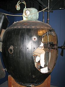
The Date is: September 7, 1776
On September 7, 1776, during the Revolutionary War, the American submersible craft Turtle attempts to attach a time bomb to the hull of British Admiral Richard Howe’s flagship Eagle in New York Harbor. It was the first use of a submarine in warfare. See Figure 4.14.
Figure 4.14 “Turtle”
Source: (Roland, 1977)
Results: Submarines, Submarine warfare, NAVSEA, precision munitions’, improved propulsion, nuclear -power, UXO, 1.3 Trident National Defense, advanced underwater technologies, Sonar applications, EO applications, extreme depth investigations, Search & Rescue, Sensors that work underwater and extreme conditions, pre-positioning of marine / maintenance platforms, oil exploration, and treasure hunting.
There will always be wars – somewhere. Chances are the US will be involved directly or selling munitions to a proxy. Terrorists might realize that mining the shipping areas is easier than naval ship warfare and its cost effective.[13] Sensors that work effectively underwater in hostile conditions!! This is amazing to say the least. Anyone who owns a recreational boat knows that they have to regularly clean the hulls of their boats and replace electronics 5x faster than the normal homeowner. Seawater is unforgiving to electronic and human life. UUVs and USVs handle DDD work so much better.
Just like UAS is revolutionizing the airline industry for all applications – especial defense, so will UUVs and USVs revolutionize the marine industries in both civilian and military applications. Bank on it.
Questions
- Where do you see the next Black Swan event involving UUVs?
- How might this technology be used to discover, recover, classify ancient artifacts?
- How might UUVs be used to repair data communications cables at severe depths and tangled in unground obstructions?
- Design a CONOP experiment for Counter UUV operations in foreign waters beyond claimed territorial rights.
References
B-47 Stratojet. (2020 December 17) Retrieved from: https://sk.wikipedia.org/wiki/Boeing_B-47_Stratojet
Bernstein, R. A. (29 June 2012). MUNITIONS DETECTION USING UNMANNED UNDERWATER VEHICLES EQUIPPED WITH ADVANCED SENSORS. Panama City, FL: NSWC PCD ESTCP Project Number MR-201103 Ver 7a.
Black Swan Definition. (2020, December 16). Retrieved from https://www.investopedia.com/terms: https://www.investopedia.com/terms/b/blackswan.asp#:~:text=A%20black%20swan%20is%20an,they%20were%20obvious%20in%20hindsight.
Bluefin Robotics. (2020, December 15). Retrieved from gdmissionsystems.com/underwater-vehicles/bluefin-robotics: https://gdmissionsystems.com/underwater-vehicles/bluefin-robotics
Crouch, T. (2014, March). history-of-flight/wright-brothers-first-flight-photo. Retrieved from www.airspacemag.com: https://www.airspacemag.com/history-of-flight/wright-brothers-first-flight-photo-annotated-180949489/
- Sulzberger, J. B. (2009). Hunting Sea Mines with UUV-Based Magnetic and Electro-Optic Sensors. Retrieved from algebra.sci.csueastbay.edu/: http://algebra.sci.csueastbay.edu/~grewe/pubs/DistSensorNetworkBook2011/Atmosphere/UnderWaterSeaMineHunt.pdf
Kovacs, T. (1998). Micromachined Transducers Sourcebook. NYC: McGraw-Hill.
Leasko, R. (2014). Munitions Detection Using Unmanned Underwater Vehicles Equipped with Advanced Sensors. Scotts Valley, CA: CreateSpace Independent Publishing Platform (Amazon Media on Demand).
Naval Mines. (2020, December 16). Retrieved from en.wikipedia.org: https://en.wikipedia.org/wiki/Naval_mine#cite_note-minewar-83
Nichols, R. K. (2019, October 15). Randall Nichols (October 15, 2019) Implications from Attack by Iran on Saudi Arabian Oil Fields (implications-from-attack-iran-saudi-arabian-oil-fields-nichols. Retrieved from www.linkedin.com/pulse/: https://www.linkedin.com/pulse/implications-from-attack-iran-saudi-arabian-oil-fields-nichols/
Nichols, R. K., Mumm, H. C., Lonstein, W. D., Ryan, J. J., Carter, C. M., & & Hood, J. P. (2020). Counter Unmanned Aircraft Systems Technologies & Operations. Manhattan, KS: New Prairie Press #31.
Nichols, R. K., Mumm, H. C., Lonstein, W. D., Ryan, J. J., Carter, C., & and Hood, J.-P. (2019). Unmanned Aircraft Systems in the Cyber Domain, 2nd Edition. Manhattan, KS: NPP eBooks. 27. Retrieved from www.newprairiepress.org/ebooks/27
Nichols, R., Ryan, J., Mumm, H., Lonstein, W., Carter, C., & & Hood, J. (2019). Unmanned Aircraft Systems (UAS) in Cyber Domain: Protecting USA’s Advanced Air Assets, 2nd Edition. Manhattan, KS: New Prairie Press #27 .
NSWC. (2020, December 15). Warfare Centers NSWC Panama City. Retrieved from www.navsea.navy.mil: https://www.navsea.navy.mil/Home/Warfare-Centers/NSWC-Panama-City/What-We-Do/
Ocean Studies Board, N. R. (2012). Oceanography and Mine Warfare. Washington, DC: Ocean Studies Board, National Research Council ISBN 0-309-51587-4.
Randall K. Nichols, D. J. (2000). Defending Your Digital Assets against Hackers, Crackers, Spies and Thieves. New York: RSA Press.
REMUS -1. (2020, December 15). REMUS 100 Technical Brochure (2017). Retrieved from www.hydroid.com: https://www.hydroid.com/sites/default/files/product_pages/New_Generation_REMUS_100_%20Brochure_2017.pdf
REMUS -2. (2020, December 15). REMUS 600 Technical Data. Retrieved from www.hydroid.com/remus-600-defense-applications: https://www.hydroid.com/remus-600-defense-applications
REMUS. (2020, December 15). REMUS 100 for Defense Applications Data Sheet. Retrieved from https://www.hydroid.com/new-generation-remus-100-defense-applications: https://www.hydroid.com/new-generation-remus-100-defense-applications
REMUS -3. (2020, December 15). REMUS 600 Technical Data Sheet. Retrieved from www.hydroid.com/: https://www.hydroid.com/sites/default/files/product_pages/REMUS_600_Brochure_2017_0.pdf
REMUS -4. (2020, December 15). REMUS 6000 . Retrieved from www.hydroid.com/: https://www.hydroid.com/sites/default/files/product_pages/REMUS_6000_Brochure_2017.pdf
REMUS -5. (2020, December 15). REMUS 6000 Brochure. Retrieved from www.hydroid.com/: https://www.hydroid.com/sites/default/files/product_pages/REMUS_6000_Brochure_2017.pdf
Roland, A. (1977). Bushnell’s Submarine: American Original or European Import? Technology and Culture: The Johns Hopkins University Press, Vol. 18, No. 2 (Apr., 1977), pp. 157-174 (18 pages).
SERDP-ESTCP. (2012). Munitions-Response/Munitions-Underwater/MR-201103-IR. https://www.serdp-estcp.org/Program-Areas/Munitions-Response/Munitions-Underwater/MR-201103: NSWC PCD.
Teledynemarine. (2020, December 16). Q-Boat_1250. Retrieved from www.teledynemarine.com: http://www.teledynemarine.com/Q-Boat_1250?BrandID=13
Teledynemarine-1. (2020, December 16). Z-Boat1800T_Trimble. Retrieved from www.teledynemarine.com: http://www.teledynemarine.com/Z-Boat1800T_Trimble?BrandID=13
[1] Black Swan Event- A black swan is an unpredictable event that is beyond what is normally expected of a situation and has potentially severe consequences. Black swan events are characterized by their extreme rarity, severe impact, and the widespread insistence they were obvious in hindsight. (Black Swan Definition, 2020)
[2] The type of precision on sensors that work effectively underwater is an interesting science in itself. A primary reference on the subject is by Kovacs entitled “Micromachined Transducers Sourcebook.” (Kovacs, 1998) There are many newer references, but students should start with this one to get a fundamental basis for the construction of specialized sensors before jumping into the next step in the process.
[3] (Leasko, 2014)Published in 2014 means that we are 6-7 years behind further advances in the sensors and hardening capabilities of the assets. However, students can get a lot of information and strategy from this UNCLASSIFIED report to chew on. This is why the author chose it as a primary reference for this chapter.
[4] The inventory has been obviously expanded and upgraded since this NSCW PCD evaluation. However, those upgrades have been in the sensor technologies not necessarily the UUV packages they arrive in. Concentrate on the beauty of being able to solve such a MCM detection / assessment / classification problem (underwater, cold temperatures, hostile environment, visibility issues, salt(s) corrosion, significant pressures, magnetic and electro-optic interferences, to name a few variables.)
[5] BOSS data will be collected over the seeded areas and analysis will follow to identify the number of targets detected by the system. The number of targets detected by the BOSS system will be cataloged and verified against the target listing and ground truth localization provided by the divers. (SERDP-ESTCP, 2012)
[6] Pd = Probability of Detection
[7] The magnetic moment is estimated by statistically fitting windowed time series to a magnetic-dipole model. The properties of the moment, including dipole strength and orientation, are extracted in this process. (SERDP-ESTCP, 2012)
[8] RTG/LSG data will be collected over the seeded areas and analysis will follow to identify the number of targets detected by the system. The number of targets detected by the RTG/LSG system will be cataloged and verified against the target listing and ground truth localization provided by the divers. (SERDP-ESTCP, 2012)
[9] The effectiveness of the RTG/LSG localization of proud to fully buried ferrous targets. (SERDP-ESTCP, 2012)
[10] Metric: Compare the RTG/LSG target localization with the diver provided target ground truth and determine the percentage of BOSS detections of seeded targets that can be identified as non-ferrous using RTG/LSG data. & Data Requirements:
RTG/LSG data will be collected over the seeded areas and analysis will follow to identify and localize the targets of interest. The RTG/LSG localization for each target will be cataloged and verified against the target listing and ground truth localization provided by the divers. (SERDP-ESTCP, 2012)
[11] Post Mission Analysis (PMA)
[12] Disclaimer: Author has no financial or legal relationship to vendors discussed in this chapter. Interest is purely technical.
[13] An example of this in the Straight of Hormuz which 5% of the world’s oil transportation and gas purification processes are located. See author article on missile effects as a another POV: (Nichols R. K., Randall Nichols (October 15, 2019) Implications from Attack by Iran on Saudi Arabian Oil Fields (implications-from-attack-iran-saudi-arabian-oil-fields-nichols, 2019)
