3 Space Electronic Warfare, Signal Interception, ISR, Jamming, Spoofing, & ECD (NICHOLS & MAI)
Student Objectives
Space is the new frontier of electronic warfare (EW), intelligence, and reconnaissance. Space is also the place to view the earth in large “earth traces.” These views can help military and agricultural planners make better decisions on protecting the United States and managing (increase) global food supply, land usage, irrigation, and health. The same information for diametrically different uses. This chapter is concerned with the former. We peruse:
- Key definitions in EW, satellite systems, and ECD countermeasures
- A look at space calculations and satellite threats using plane and spherical trigonometry to explain orbital mechanics
- A brief review of EMS, signals, RADAR, Acoustic, and UAS Stealth principles,
- Signals to/from satellites and their vulnerabilities to Interception, Jamming, and Spoofing,
- Signals to/from satellites and their vulnerabilities to Interception, Jamming, and Spoofing
- The promising ECD technology countermeasure to spoofing can detect, mitigate, and recover fake and genuine signals.
EW Definitions [1]
Electronic Warfare (EW) is the art and science of denying an enemy the benefits of the electromagnetic spectrum (EMS) while preserving them for friendly forces. (Wolff, 2022)
Signals Intelligence (SIGINT) is the analysis and identifying intercepted transmissions, including frequency, bandwidth, modulation (“waveform”), and polarization. Four categories of SIGINT are: (Wolff, 2022)
- Electronic Intelligence (ELINT)
- Communications Intelligence (COMINT)
- Foreign instrument SIGINT (FISINT)
- Measurement intelligence (MASINT) Covered in Chapter 10 of DRONE DELIVERY OF CBNRECy – DEW WEAPONS Emerging Threats of Mini-Weapons of Mass Destruction and Disruption (WMDD) (Nichols & Sincavage, 2022)
EW Sub-Areas
Electronic Warfare Support (EWS/ES) measures detection, intercept, identification, location, and localizes sources of intended and unintended radiated electromagnetic (EM) energy. (Wolff, 2022)
Activities related to ES include:
- Electronic Reconnaissance: location, identification, and evaluation of foreign electromagnetic radiation
- Electronic intelligence: Technical and geolocation intelligence derived from foreign non-communications electromagnetic radiation emanating from sources other than nuclear detonations or radioactive sources
- Electronics security: protection resulting from all measures designed to deny unauthorized persons information of value that might be derived from the interception and study of non-communications electromagnetic radiation, e.g., radar. (Wolff, 2022)[2]
Electronic Attack (EA) activities – may be either offensive or defensive and include: (Wolff, 2022)
- Countermeasures: employment of devices and/or techniques that has as their objective the impairment of the operational effectiveness of enemy activity
- Electromagnetic deception: Covered in Chapter 7 of DRONE DELIVERY OF CBNRECy – DEW WEAPONS
- Emerging Threats of Mini-Weapons of Mass Destruction and Disruption (WMDD) (Nichols & Sincavage, 2022) Various EM deception techniques, such as a false target or duplicate target generation, confuse the enemy intelligence, surveillance, and reconnaissance systems (ISR). (Wolff, 2022)
- Electromagnetic intrusion: is the intentional insertion of EM energy (EME) into transmission paths in any manner to deceive operators or to cause confusion.
- Electromagnetic jamming is deliberate radiation, reradiation, or reflection of EME to prevent or reduce an enemy’s effective use of the EMS and with the intent of degrading or neutralizing the enemy’s combat capability.
- Electromagnetic pulse is EM radiation from a strong electronic pulse [Directed energy weapons (DEW)] that may couple with electrical or electrical systems to produce damaging current and voltages. (Wolff, 2022)Chapters 9-11 in DRONE DELIVERY OF CBNRECy – DEW WEAPONS Emerging Threats of Mini-Weapons of Mass Destruction and Disruption (WMDD) expertly cover the subject. (Nichols & Sincavage, 2022)
- Electronic probing is intentional radiation designed to be introduced into the devices and systems of potential enemies to learn the operational capabilities of the devices and systems.
- Cyber or electronic spoofing: – A Cyber-weapon attack that generates false signals to replace valid ones. GPS Spoofing is an attack to provide false information to GPS receivers by broadcasting counterfeit signals similar to the original GPS signal or by recording the original GPS signal captured somewhere else at some other time and then retransmitting the signal. The Spoofing attack causes GPS receivers to provide the wrong information about position and time. (T.E. Humphrees, 2008) (Tippenhauer & et.al, 2011) (Nichols & Sincavage, 2022)
Electronic protection measures (EP): EP measures fall into six categories: (Wolff, 2022)
EM hardening: actions are taken to protect personnel, facilities, and or equipment by blanking, filtering, attenuating, grounding, bonding, and shielding against undesirable effects of EME.
Electronic masking: controlled radiation of EME on friendly frequencies to protect the emissions of friendly communications and electronic systems against enemy EWS measures and SIGINT without significantly degrading the operation of friendly systems.
Emission control: sensitive and controlled use of EM, acoustic, or other emitters to optimize command and control (C2) capabilities while minimizing the following for operations security (OPSEC): 1) detection by enemy sensors; 2) mutual interference among friendly systems; 3) enemy interference with the ability to execute a military deception plan. (Wolff, 2022)
EMS management: planning, coordinating, and managing joint use of the EMS through operational, engineering, and administrative procedures.
Wartime reserve modes: characteristics and operating procedures for sensors, communications, navigation aids, threat recognition, weapons, and countermeasures systems that will contribute to military effectiveness if unknown to or misunderstood by opposing commanders before they are used but could be exploited or neutralized if known in advance. (Wolff, 2022)
EM compatibility: the ability of systems, equipment, and devices that use the EMS to operate in their intended environments without causing or suffering unacceptable or unintentional degradation because of electromagnetic radiation (EMR) or response. (Wolff, 2022) This is an extremely important concept and is exploited by the use of UAS against USN assets in the South China Seas (SCS.) (Nichols & al., 2020)
ISR – Intelligence, Surveillance, and Reconnaissance [3]
Intelligence, surveillance, and reconnaissance operations (ISR) are used to collect information about the enemy, terrain, weather, and other aspects of the Area of Operation (AO) that will affect friendly combat operations. (Global Security.Org, 2022)
The Army has conducted reconnaissance and surveillance tasks since its inception. The production of intelligence (the product resulting from the collection, processing, integration, analysis, evaluation, and interpretation of available information concerning an enemy force or area of operation) has always been critical to successfully accomplishing the mission. ISR is the term currently applied to combined arms enabling operation that combines previously described as reconnaissance and surveillance (a maneuver or collection task) with the production and dissemination of intelligence (a staff task). ISR is a constant, continuous, and optimized operation that focuses on the collection of relevant information that is analyzed to create intelligence to support the commander’s and or leader’s situational understanding and the operational cycle. (Global Security.Org, 2022)
ISR Systems and Technology from Space
MIT gives an interesting purview of their mission for ISR from space. They see it as “Creating Technology To Provide Vital Tactical Information.” They conduct “R&D in advanced sensing, signal and image processing, decision support technology, and high-performance embedded computing to provide systems capable of gathering reliable intelligence, surveillance, and reconnaissance information.” (MIT R&D, 2022) It is this purview that the authors see from the user POV to develop “earth traces” from space capable of yielding unique information on non-military technologies such as agriculture management, crop rotation, global food supply, tree and fire zone management, and cattle management.
Eichelberger Collective Detection (ECD) Definitions / Counter Spoofing Concepts
Acquisition – Acquisition is the process in a GPS receiver that finds the visible satellite signals and detects the delays of the PRN sequences and the Doppler shifts of the signals.
Circular Cross-Correlation (CCC) – In a GPS classical receiver, the circular cross-correlation is a similarity measure between two vectors of length N, circularly shifted by a given displacement d:
[latex]cxcorr(a,b,d) = \sum_{i=0}^{N-1} a_i \cdot b_{i+d\bmod N}[/latex] Eq. 3-1
The two vectors are most similar at the displacement d, where the sum (CCC value) is maximum. The vector of CCC values with all N displacements can be efficiently computed by a fast Fourier transform (FFT) in Ớ ( N log N ) time. [4](Eichelberger, Robust Global Localization using GPS and Aircraft Signals, 2019)
Like classical GPS receivers, coarse-Time Navigation (CTN) is a snapshot receiver localization technique that measures sub-millisecond satellite ranges from correlation peaks. (IS-GPS-200G, 2013) [See also expanded definition above.]
Collective Detection (CD) is a maximum likelihood snapshot receiver localization method, which does not determine the arrival time for each satellite but combines all the available information and decides only at the end of the computation. This technique is critical to the (Eichelberger, Robust Global Localization using GPS and Aircraft Signals, 2019) invention to mitigate spoofing attacks on GPS or ADS-B.
Coordinate System – A coordinate system uses an ordered list of coordinates to uniquely describe the location of points in space. The meaning of the coordinates is defined concerning some anchor points. The point with all coordinates being zero is called the origin. [ Examples: terrestrial, Earth-centered, Earth-fixed, ellipsoid, equator, meridian longitude, latitude, geodetic latitude, geocentric latitude, and geoid. [5]
Localization – Process of determining an object’s place concerning some reference, usually coordinate systems. [aka Positioning or Position Fix]
Navigation Data is the data transmitted from satellites, which includes orbit parameters to determine the satellite locations, timestamps of signal transmission, atmospheric delay estimations, and status information of the satellites and GPS as a whole, such as an accuracy and validity of the data. (IS-GPS-200G, 2013) [6]
Pseudo-Random Noise (PRN) sequences are pseudo-random bit strings. Each GPS satellite uses a unique PRN sequence with a length of 1023 bits for its signal transmissions. Aka as Gold codes, they have a low cross-correlation with each other. (IS-GPS-200G, 2013)
Snapshot GPS Receiver– A snapshot receiver is a global positioning satellite (GPS) receiver that captures one or a few milliseconds of raw GPS signal for a location fix. (Diggelen, 2009)
Scope
Looking at the definitions above, the EW and ECD spheres are huge and encompass many different sciences. Chapter 3 focus will be on space electronic warfare with a limited scope and a specific emphasis on spoofing. We are trying to get a sense of the technologies and challenges. Jamming will be briefly presented only as a precursor attack to a spoofing attack. There are plenty of learning seminars available by SMEs like Rhode & Schwartz and fundamental textbooks to inform the reader. (Wolff, 2022) (Adamy D. , EW 101: A First Course in Electronic Warfare, 2001) (Adamy D. L., Space Electronic Warfare, 2021) (Adamy D. L., EW 104: EW against a new generation of threats, 2015) (Adamy D. L., EW 103: Tactical Battlefield Communications Electronic Warfare, 2009) (Adamy D. L., 2004)[7] [8]
Decibel Math
EW calculations are done using “dB” math. It allows manipulation of very large numbers such as transmitted signal strength and very small numbers such as received signal strength. Numbers expressed in decibels (or dB) form are logarithmic and follow the rules.[9] This permits the comparison of values that may differ in many orders of magnitude. It is important to understand that any value expressed in decibel units is a ratio converted to a logarithmic form. (Adamy D. , EW 101: A First Course in Electronic Warfare, 2001)
To Convert To Decibel Form (base 10 log)
Ratio (in dB) = 10 log (Linear Ratio) Eq. 3-2
Example: convert 2 (the ratio of 2 to 1) to decibel form.
[latex]10\log(2)=3{dB}[/latex] (rounded)
convert 1/2 (the ratio of 1 to 2) to decibel form.
[latex]10\log(0.5)=-3{dB}[/latex] in EW, link loss and antenna calculations this is a useful factor.
A reverse way of looking at the process or converting back to a nonlogarithmic form is:
Antilog (logarithm number) = linear number in place of 10 (logarithmic number)
So, antilog (3/10) = 2. See (Adamy D. , EW 101: A First Course in Electronic Warfare, 2001) or (Adamy D. L., 2004) or (Adamy D. L., Space Electronic Warfare, 2021) for many examples of nauseating details and helpful tables for common usage.
Plane Trig /Equations
To solve problems of elevation and azimuth of look angles associated with Earth Satellites, three-dimensional (3-D) angular relationships are solved with Plane and Spherical Trigonometry. Plane Trigonometry deals with triangles in a plane. The important relationships are:
Plane Trigonometry:
The Law of Sines: [latex]a/\sin A = b/\sin B = c/\sin C[/latex] Eq. 3-3
Note: Lower case letters represent the lengths of a triangle’s side, and upper-case letters are their associated angles opposite the corresponding side.
[latex]a^{2} = b^{2} + c^{2} - 2bc\ cos A[/latex] Eq. 3-4
The Law of Cosines for Angles: [latex]A = b\cos C + c\cos B[/latex] Eq. 3-5
A right triangle is a plane triangle with a 90° angle. All triangles fall under the above rules.
Right Triangle: 2-dimensional defined, also known as a Plane Triangle.
Figure 3-1 Right Triangle

Source: (Adamy D. L., Space Electronic Warfare, 2021)
Spherical Trigonometry:
The Law of Sines for Spherical Triangle:
[latex]\sin a / \sin A = \sin b / \sin B = \sin c / sin C[/latex] Eq. 3-6
The Law of Cosines for Sides:
[latex]\cos a=\cos B \cos C + \sin B\sin C\cos a[/latex] Eq. 3-7
The Law of Cosines for Angles:
[latex]\cos A = -\cos B \cos C + \sin B \sin C \cos a[/latex] Eq. 3-8
Spherical Triangle: Formed by 3 great circles that pass through a common center point.
Figure 3-2 Triangle on a Sphere

Source: (Adamy D. L., Space Electronic Warfare, 2021)
Napier’s Rules:
Right spherical triangles allow the use of simplified spherical trigonometric equations using Napier’s rules.
Figure 3-3 Napier’s Rules for Right Spherical Triangles

Source: Author modification of Figure 2.6 in (Adamy D. L., Space Electronic Warfare, 2021)
Rules for Napier’s right spherical triangles
[latex]\sin a =\tan b \cot B[/latex] Eq. 3-9
[latex]\cos A = \cot c \tan b[/latex] Eq. 3-10
[latex]\cos c = \cos a \cos b[/latex] Eq. 3-11
[latex]\sin a=\sin A\sin c[/latex] Eq. 3-12
Orbital Mechanics
Spherical and Elliptical geometry explain Orbital Mechanics. The difficulty trying to understand Spherical Triangles versus Plane Triangles is because Spherical Triangles are 2-dimensional, taking place on a sphere rather than a plane. An example would be looking at a map and drawing a line from one point to the other, r but in reality, the space between is actually curved. Spherical Trigonometry takes the curvature of the earth into account. This is known as the Keplerian ephemeris. The Ephemeris elements of Spherical Triangles can be seen in Table 3-1.
Table 3-1
Earth Satellite Ephemeris
| Ephemeris Value | Significance | |
| a | Semi-major Axis | Size of the Orbit |
| e | Eccentricity | Shape of the Orbit |
| i | Inclination | Tilt of orbit relative to the equatorial plane |
| Ω-θ = n | Right ascension of the ascending node | Longitude at which the satellite crosses the Equator going north |
| w | Argument of Perigee | Angle between ascending node and perigee |
| v | True anomaly | Angle between perigee and the satellite Location in the Orbit |
Note: Apogee = a(1-e) Source: (Adamy D. L., Space Electronic Warfare, 2021)
Figure 3-4 The Ephemeris defines the satellite’s location with six factors.
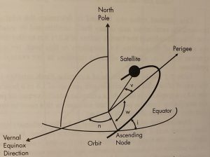
Source: Courtesy of (Adamy D. L., Space Electronic Warfare, 2021)
From the orbital elements, it is possible to compute the position and velocity of the satellite.
Kepler’s Third Law states the relationship between the size of the orbit and its period is defined by:
[latex]a^{3} = CP^{2}[/latex] Eq. 3-13
where: a = the semi-major axis of the orbit ellipse, C is a constant, and P = the orbit period.
Example: If a Satellite circles the Earth every 1.5 hours and has an altitude of 281.4-km-high (or a radius from the center of the Earth of 6,653 km, then C is calculated as; 6,653 km3/90 min2 = 36,355.285 km per min2
Table 3-2 Shows the altitude of a circular Earth satellite versus the period of its orbit for satellites with periods of 1.5 hours to 9 hours.
Altitude and Semi-Major Axis of Circular Orbits Versus the Satellite Period
| p(min) | h(km) | α(km) | p(min) | h(km) | α(km) |
| 90 | 281 | 6652 | 330 | 9447 | 15818 |
| 105 | 1001 | 7372 | 345 | 9923 | 16294 |
| 120 | 1688 | 8059 | 360 | 10392 | 16763 |
| 135 | 2346 | 8717 | 375 | 10854 | 17225 |
| 150 | 2980 | 9351 | 390 | 11311 | 17682 |
| 165 | 3594 | 9965 | 405 | 11761 | 18132 |
| 180 | 4189 | 10560 | 420 | 12206 | 18577 |
| 195 | 4768 | 11139 | 435 | 12646 | 19017 |
| 210 | 5332 | 11703 | 450 | 13081 | 19452 |
| 225 | 5883 | 12254 | 465 | 13510 | 19881 |
| 240 | 6422 | 12793 | 480 | 13936 | 20307 |
| 255 | 6949 | 13320 | 495 | 14357 | 20728 |
| 270 | 7466 | 13837 | 510 | 14773 | 21144 |
| 285 | 7974 | 14345 | 525 | 15186 | 21557 |
| 300 | 8473 | 14844 | 540 | 15595 | 21966 |
| 315 | 8964 | 15350 | – | – | – |
Source: (Adamy D. L., Space Electronic Warfare, 2021)
Figure 3-5 Altitude of a Circular Satellite is a Function of its Orbital Period
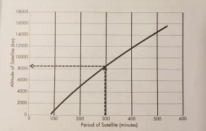
Source: (Adamy D. L., Space Electronic Warfare, 2021)
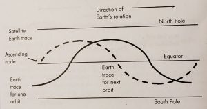
EARTH TRACES
Figure 3-6 Earth traces of synchronous satellites as they travel in sine wave over a global map
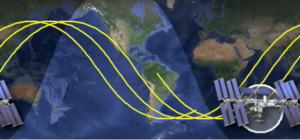
Source: (CYFO: A, 2018)
If you have ever wondered why satellites look like they travel in a sine-wave along a global map, you are not alone. It seems counterintuitive; however, there is an easy explanation for this. First, remember that a global is not a flat surface. Although the above map is in 2-dimensions and Earth traces of a satellite are represented in a sine wave, making them look as though they do not travel in a straight line. Why are they represented this way?
If we take a piece of paper, draw a straight line in the center, and label it as the equator, we will find out that it is the only straight line on a 2-dimensional map.
Figure 3-7 Representation of the Equator on a 2-dimensional paper

Source: Hand drawn by co-author Mai, R. (2022)
Now, as we fold the piece of paper into a circle, we see that the line creates a circle. It does not create the sine wave that we see in the first map above.
Figure 3-8 Representation of the Equator on a circular rolled 3-dimensional paper.

Source: Hand drawn by co-author Mai, R. (2022)
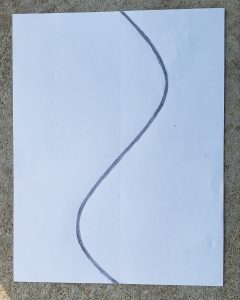
However, by working backwards through this problem, by drawing a circle on the folded paper in any other inclination, we do not have a result that creates a straight line.
Figure 3-9 Representation of any inclination as a sine wave on circular rolled 3-dimensional paper- represent a satellite’s Earth traces.

Source: Hand drawn by co-author Mai, R. (2022)
Instead, a sine wave is formed when unfolded and laid flat, just like in the picture above. This is how a sine wave is formed when trying to represent a satellite Earth traces in 2-dimensional form. Even though the satellite travels in a straight line when circling a globe. To represent its travel in 2 dimensions, this is the result. It is true for all angles other than the equator.
When unfolded, you can see where the sine wave is created.
Figure 3-10 The Earth trace is the locus of latitude and longitude of the SVP as the satellite moves through its orbit.
Source: Hand drawn by co-author Mai, R. (2022)
LOOK ANGLES
The Earth trace is the locus of latitude and longitude of the SVP as the satellite moves through its orbit. Note: The SVP is the point on the Earth’s surface directly below the satellite. This point intersects the line from the center of the Earth to the satellite with the surface of the Earth. LEO (low earth orbits) determines the moment-to-moment area of the Earth that the satellite sees. It also allows us to calculate the look angles and range of the satellite from a specified point on (or above) the Earth at any specified time.
A recent example of a satellite monitoring Lake Meade water loss since 2000, looking towards the SVP. It shows before and after.
Figure 3-11 Lake Meade before water loss 2000 Figure 3-12 Lake Meade after water loss 2021


Source for Figure 3-11 & 3-12: (Data: USGS/NASA Landsat, 2021)
Using the six elements of Ephemeris (defined earlier in the chapter) the exact location of a satellite can be calculated at any time. For example, the Earth trace of a satellite with a 90-minute orbital period will move West by 22.56 longitude degrees for each subsequent orbit.
Example: (90-minute orbital Period / 1463 sidereal day, minutes) x 360 deg = 22.56 deg
Figure 3-13 Earth trace of the satellite is the path of the SVP over the Earth’s surface in Polar view.
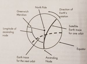
Source: Courtesy of (Adamy D. L., Space Electronic Warfare, 2021)
Where: (SVP = Sub-vehicle point) and is the intersection of a line from the center of the Earth to the satellite with the Earth’s surface
The Earth area over which a satellite can send or receive signals to and from the Earth-based stations during each orbit depends on the altitude of the satellite and the beam width and orientation of antennas on the satellite. If a satellite is placed in polar orbit, its orbit has 90֩ inclination and will therefore eventually provide complete coverage of the surface of the Earth.
Figure 3-14 Earth trace of a satellite is the path of the SVP over the Earth’s surface in equatorial view.
Source: Courtesy of (Adamy D. L., Space Electronic Warfare, 2021)
A synchronous satellite has an SVP that stays in one location on the Earth’s surface. This requires that its orbital period be one sidereal day (i.e., 1,436 minutes). Another requirement for a fixed SVP is that the orbit has an 0° inclination. That would place it directly on the border.
Figure 3-15 Example calculation: Maximum Range to a synchronous satellite on the horizon is 41,759 km by Kepler’s Laws. Link loss for a 2 GHz signal would be from 189.5 to 190.9 dB
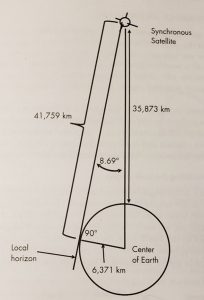
Source: Courtesy of (Adamy D. L., Space Electronic Warfare, 2021)
Figure 3-15 shows a sample calculation of the range of a synchronous satellite based on a semi-major axis of 42,166 km. “In a circular orbit, the satellite’s height will be 35,795 km. The maximum range can be calculated from the Earth surface station (ESS) to the synchronous satellite with a circular orbit. The diagram is a planer triangle in the plane containing the ESS, satellite, and center of Earth. The ESS sees the satellite at 0 deg elevation. The minimum and maximum range values for the satellite to the ground link are 35,795 km and 41,682 km. The shorter range applies if the satellite is directly overhead, and the maximum range is for the satellite to the horizon as shown.” (Adamy D. L., Space Electronic Warfare, 2021)
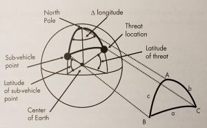
Location of Threat to Satellite
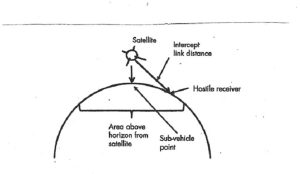
The location of a threat from the satellite is defined in terms of the azimuth and elevation of a vector from the satellite that points at the threat location and the range between the satellite and the threat. The vector points information for a satellite antenna aimed at the threat. An EW system on the satellite will either intercept signals from a threat transmitter or transmit jamming signals to a threat receiver at the considered location.
Figure 3-16 The azimuth and elevation angle from the nadir defines the direction of a threat to a satellite.
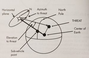
Source: Courtesy of (Adamy D. L., Space Electronic Warfare, 2021)
Where: the azimuth is the angle between true North and the threat location in a plane at the satellite perpendicular to the vector from the SVP. The elevation is the angle between the SVP and the threat. The nadir is defined as the point on the celestial sphere directly below an observer.
Calculating the Look Angles:
For the azimuth calculation, we need to consider the spherical triangle.
Figure 3-17 A spherical triangle is formed between the North Pole, the SVP, and the Threat location.
Source: Courtesy of (Adamy D. L., Space Electronic Warfare, 2021)
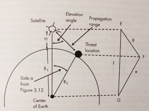
The elevation from the nadir and range to a threat from a satellite can be determined from the plane triangle defined by the satellite, the threat, and the center of the Earth. For example, Set E is at the satellite, F is at the threat, and G is at the center of the Earth. Side e is the radius of the Earth (6,371 km). Side f is the semi-major axis (the radius of the Earth plus the satellite altitude = 10,560 km), angle G is side a from the spherical triangle above (21.57°), and side g is the propagation distance between the satellite and the threat.
The law of cosines for plane triangles is:
[latex]g^{2}=e^{2} + f^{2} -2ef\cos(G)[/latex] Eq. 3-14
Figure 3-18 The elevation from the nadir and range to a threat from a satellite can be determined from the plane triangle defined by the satellite, threat, and the center of the Earth.
Source: Courtesy of (Adamy D. L., Space Electronic Warfare, 2021)
EMS
Chapter 8 Designing UAS Systems for Stealth in Unmanned Aircraft in the Cyber Domain, 2nd ed. (Nichols R. K.-P., 2019) the author’s introduced the Electromagnetic Spectrum in relationship to battlefield dimensions and stealth signatures for unmanned aircraft systems (UAS). We will start with a short replay of this information because the coverage was instructive.
Designing a UAS for Stealth
Stealth means “to resist detection.” Stealth applies to the air vehicle and materials visible to the enemy plus the internal sense and avoid systems (SAA) that control / create noise, heat, electromagnetic emanations, and changes in light. For intelligence, reconnaissance, and surveillance (ISR) platforms and missions, the UAS systems must be undetected in operation. “It is desirable not to alert the enemy (military) or criminals (police) to the ISR operation.” It can be assumed that the enemy is using counter-UAV [10]operations and weapons. Stealth design protects the air vehicle from these counter – UAV measures. Stealth in civilian operations results in minimal environmental disturbances. (Austin, 2010)
Detection Signatures
Their signatures detect UAS / UAVs: noise (acoustic), optical (visible), infrared (thermal) and radar (radio). “These acoustic or electromagnetic emissions occur at the following wavelengths: (Austin, 2010)
Noise (acoustic) [16 m-2 cm, or 20 – 16000 Hz]
Optical (visible) [0.4 – 0.7 um]
Infrared (thermal) [0.75 um – 1 mm]
RADAR (radio) [3 mm – 3 cm]” (Austin, 2010)
If the designer is to “reduce the vehicle detectability to an acceptable risk level, it is necessary to reduce the received emissions or reflection of the above wavelengths (expressed as frequencies) below the threshold signature value. A good portion of the UAS signatures is a function of the operating height of air vehicle.” (Austin, 2010)
A student might look at the answers above and ask what the significance is? Let’s take a short sojourn down the EMS lane. Military planners used to think about ground, sea, and air. Space came later. Now there is a “fifth realm,” the electromagnetic spectrum (EMS). For EMS, we think in terms of frequency. Enhancing our ability to communicate using the EMS significantly changes how we conduct warfare. (Adamy D. -0., 2015) (Adamy D. L., Space Electronic Warfare, 2021)
Radio communications and wireless transmissions using tuned transmitters and the information explosion of the internet were the heart of the warfare revolution. The certainty of intercepting radio communications and radar signals and the ability to locate transmitters significantly impacted military operations. Intercept, jamming, spoofing, emitter location, message security, and transmission security became fundamental to warfare. The basic destructive capabilities (energy) employed in warfare have not changed greatly (fast-moving projectiles, significant overpressure, heat, and sound). However, the ways they are employed have changed significantly through the use of the EM Spectrum (EMS). Now, we guide the destructive energy of weapons towards their intended targets using the EMS in many ways. Also, the EW specialist uses EMS to prevent those weapons from hitting their intended targets. Sometimes the destruction of communications capability by an enemy is the goal.
The battlespace, which once had only four dimensions (latitude, longitude, elevation, and time [before radio]), now has a fifth dimension: frequency. (Adamy D. -0., 2015) See Table 3-2 Battlespace Dimensions.
Bandwidth is defined as the range within a band of wavelengths, frequencies, or energy. Think of it as a range of radio frequencies occupied by a modulated carrier wave, assigned to a service over which a device can operate. Bandwidth is also the capacity for data transfer of electrical communications systems. The range has a significant impact on radio transmission. Depending on the environment, the strength of a received signal, T, is a function of the square or fourth power of a distance, d, from the transmitter.
Table 3-3 Battlespace Dimensions
| Dimension | Function | Action |
| Latitude | Friendly Force Location | Direction of Weapons |
| Longitude | Enemy Force Location | Maneuver of Forces |
| Elevation | ||
| Time | Speed of Maneuver | Timeliness of Attack |
| Timing of Weapon Release | Enemy Vulnerability | |
| Frequency | Bandwidth Required | Rate of Information Flow |
| Bandwidth Available | Interference | |
| Frequency of Transmissions | Vulnerability to Jamming | |
| Vulnerability to Intercept | ||
| Vulnerability to Spoofing11 |
Source: (Adamy D. -0., 2015) Reprinted from Table 8-1 in (Nichols R. K.-P., 2019)
Note the addition of a new and powerful threat vector – Spoofing.
A closer transmitter will better receive a signal and can usually locate the transmitter more accurately. Once we depend on inputs from multiple receivers, the network becomes central to our war-making ability. [ Think UAS Team collaboration.] We have now entered net-centric warfare. (Adamy D. -0., 2015) Net-Centric warfare was the brainchild of John Arquilla and David Ronfeldt of the National Defense Research Institute. See: (Ronfeldt, 1966)
Thinking again about a team or swarm of UAS, the low-hanging fruit target is US communications. (Nichols R. K., 2020)We depend on connectivity in everything we do: daily lives, social interactions, business, manufacturing, government, transportation, computers, and warfare, to name just a few in the extensive list. Connectivity is any technique for moving information from one location or player to another. Consider the economic impact of shutting our critical infrastructure (banking, air transportation, etc.). Damaging the connectivity of the system is real damage. We measure connectivity in terms of information flow. In warfare, this is called Information Operations (IO). Fundamental to IO is the frequency at which the information is transmitted or received.
Returning to the topic of stealth concerning UAS design, we note the intelligence, surveillance, reconnaissance, and weapons payload-delivery functions of UAS. These are all IO operations, and frequency is at the heart of their success against or denial by the enemy. (Nichols R. K.-P., 2019)
Electromagnetic Spectrum (EMS)
The German company, Tontechnic-Rechner-Sengpielaudio (TRS) has put together some clever tools for conversions of wavelength to frequency (and vice versa) “for Acoustic Waves (sound waves) and Radio Waves and Light waves in a vacuum.” (TRS, 2018) Start with Figure 3-19 EMS. Note the inverse relationship between frequency, f, and wavelength L (lambda – Greek).
Figure 3-19 EMS
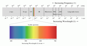
Source: (TRS, 2018) Reprinted from Figure 8-1 in (Nichols R. K.-P., 2019)
Note also how small the visible spectrum is as part of the enormous EMS. Figure 3-20 shows some of the EMS functions.
Figure 3-20 EMS Functions
Source: (TRS, 2018) Reprinted from Figure 8-2 in (Nichols R. K.-P., 2019)
Figure 3-21 shows the conversion of sound and acoustic wave period to frequency and back. (Adamy D. -0., 2015) Figure 3-22 shows the Sound EMS regions (Adamy D. -0., 2015)
Figure 3-21 Conversion for sound and acoustic wave period to frequency and back
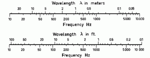
Figure 3-22 Sound EMS Regions
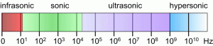
Source for Figures 3-21 & 3-22: (TRS, 2018)
Acoustic waves and Sound Waves in Air
Sound waves are EMS waves that propagate vibrations in air molecules. The 1986 standard speed of sound, c, is 331.3 m/s or 1125.33 ft/s at a temperature, T = 0 degrees Celsius.” (TRS, 2018)
The formulas and equations for sound are:
c = Lf; L = c /f = cT; f=c /L Eq. 3-15
where: T = time-period or cycle duration and T = 1/ f and f = 1 / T, T in sec, frequency is in Hertz = Hz =1/s; wavelength, L is in meters, m. The wave speed or speed of sound, c, is meters/sec, m/s. (TRS, 2018)
Noise
Austin states that the design limit for UAS Stealth for acoustic (noise) or sound waves is “[16 m-2 cm, or 20 – 16000 Hz].” (Austin, 2010) Use the TRS converter. {Basis: Speed of sound c = λ × f = 343 m/s at 20°C} for 16 m L = 21.4375Hz. This compares to the Austin value of 20 Hz. For the 2 cm = 0.02 m, the resulting valued for f = 17650 Hz. This is above the 16,000 Hz limit from Austin. This might be due to the 20-degree Celsius basis difference. This tells the UAS designer that the upper end of noise – Stealth acceptability of 17,150 Hz. The Stealth range is 20 Hz – 17,150 Hz.
Radio Waves and Light Waves in a Vacuum
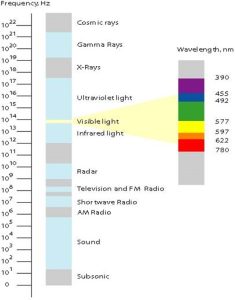
The formulas and Equations for radio and light waves in a vacuum are the same. However, the constant c is different. Lower-case c is the speed of light waves and the speed of radio waves in a vacuum. The speed of light in free space (vacuum) is the speed at which electromagnetic waves propagate, including light waves.” (TRS, 2018) Instead of the speed of sound in air, the speed of light c is 299,792,458 m/s (or 983,571,056 ft/s.) needs to be used in the formulas as the speed of propagation. Wave frequency in Hz = 1/s and wavelength in nm = 10 (**-9) m. (TRS, 2018)
Radio waves and microwave radiation are both forms of energy known as Electromagnetic Radiation (EMR). Sunlight contains other EMR forms: ultraviolet, infrared (heat) waves, and visible light waves. These EMRs spread in a vacuum at the speed of light ~ 300 000 km/s as electromagnetic radiation.” (TRS, 2018) The propagation speed of electrical signals via optical fiber is about 9/10 of c or ~270 km/s. “Copper as a medium is worse slowing the propagation speed c, to ~200, 000 km/s.” (TRS, 2018) Sound is also shown on the EMS chart but has no electromagnetic radiation. “Sound pressure is the deviation from local ambient pressure (sound pressure deviation) caused by a sound wave – mainly in air.” (TRS, 2018) Wavelength is sometimes given in Angstrom units. 1 A = 10 (**-10) m = 0.1 nm. See Figure 3-23 EMS Reduced.
Figure 3-23 EMS Reduced
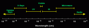
Source: (TRS, 2018)
The EMS includes visible light, gamma rays, microwaves, and radio waves. They differ by wavelength. (TRS, 2018) Figure 3-24 contains a conversion chart for radio and light waves in a vacuum.
Figure 3-24 Conversion Chart – Frequency to Wavelength Radio and Light Waves in a Vacuum [12]
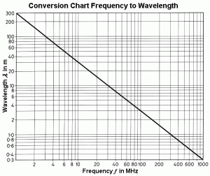
Source: (TRS, 2018)
We have covered noise, optical, and infrared stealth signatures. RADAR is not as simple without another trip down RADAR lane. RADAR was extensively discussed and written about in the 20th century. It is certainly one of the most influential inventions in the last century, arguably more relevant than the cellphone. Our concern is to “paint” or recognize the UAS signature from a distance, i.e., SPACE. If we can “see” the hostile UAS coming, it can be tracked, disabled, destroyed, intercepted, and “turned” to a new waypoint or objective.
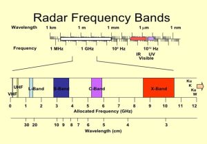
Figure 3-25 RADAR Frequency Bands (ITU, 2019)
Source: (ITU, 2019) Reprinted from (Nichols R. K.-P., 2019)
RADAR / EW / Range Equation
From Austin, we know that the upper frequency for a UAS RADAR signature is 0.03 m = 3 cm. This is approximately 10 GHz frequency. See Figure 3-25. RADAR is usually thought of in terms of Frequency Bands. See Figure 3-26 RADAR Bands and their Usage. These are consistent with the (Wolff, 2022) presentation.
Figure 3-26 RADAR Bands
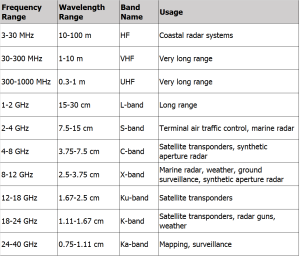
Sources: (ITU, 2019) (Wolff, 2022) Modified from Figure 8-3 in (Nichols R. K.-P., 2019)
Radio propagation theory is key to understanding Space Electronic Warfare (EW) and its role in detecting a UAS approaching a target. If we understand how radio signals propagate, we can then intercept, jam, spoof or protect in a logical progression. (Adamy D. -0., 2015) [13] (Nichols R. K., 2020)
RADAR is Radio Detection and Ranging. It uses radio waves and their propagation in the EMS to determine the battlespace elements for an approaching aircraft, UAS, ship, submarine, or any moving vehicle. We are only interested in two equations to understand the RADAR (radio) signature of a UAS. They are the link equation and the RADAR Range Equation; both are presented without derivation. “The operation of every type of RADAR, military communications, signals intelligence, and the jamming system can be analyzed in terms of individual communications links.” (Adamy D. -0., 2015) A Link includes one radiation source, one receiving device, and all events to the electromagnetic energy as it travels from source to receiver. (Adamy D. -0., 2015) (Adamy D. L., Space Electronic Warfare, 2021)
Sources and receivers can take on many forms. When a radar pulse reflects off the skin of a UAS or airplane, the reflecting mechanism is a transmitter. It obeys the same laws that apply to a walky-talky when pushing the transmit button. Yet there is no power source and no circuitry to fore reflection. (Adamy D.-9. , 1998)
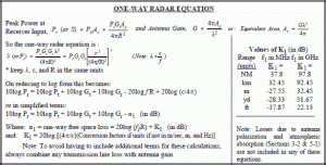
One–Way Link Equation
The basic communication link, known as a one-way link, consists of a transmitter, receiver, transmitting and receiving antennas, and propagation losses between the two antennas along the path. (Adamy D. L., Space Electronic Warfare, 2021) See Figure 3-27 Path Through One-Way Link.
Figure 3-27 Path Through One-Way Link
Sources: (Adamy D. L., Space Electronic Warfare, 2021)
The diagram shows signal strength in dBm and increases and decreases of signal strength in dB. Figure 3-27 shows the Line-of-Sight link. The transmitter and receivers can electronically see each other. However, there are interferences/exceptions. The link must not be too close to water, land, severe weather, or asymmetric non-line-of-sight propagation factors. To calculate the received signal level (in dBm), add the transmitting antenna gain (in dB), subtract the link losses (in dB), and add the receiving antenna gain (in dB) to the transmitter power (in dBm).
(Adamy D. L., Space Electronic Warfare, 2021)
A simple example of the link equation in dB format is:
Transmitter Power (1 Watt) = + 30 dBm
Transmitter Antenna Gain = +10 dB
Spreading loss = 100 dB
Atmospheric loss = 2 dB
Receiving Antenna Gain = +3 dB
Received Power = 30 dBm + 10 dB – 100 dB – 2 dB +3 dB = – 59 dBm (Adamy D.-9. , 1998)
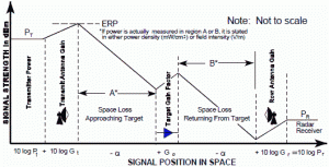
Figure 3-28 One–Way RADAR Equation
Source: Wikipedia RADAR Images
Effective Range
What is the maximum range that a RADAR can “see” a UAS in any form: individual, group, team, or Swarm? The RADAR range equations can estimate the maximum distance to detect a UAS. The smaller the UAS, the less reflective area is present to “return “a radar pulse back to its transmitter source. Figures 3-28 and 3-29 demonstrate the one-way and two-way (return trip) for determining the maximum range of a RADAR unit. The received power is equal to receiver sensitivity at the maximum link range. Receiver sensitivity is the smallest signal (lowest power strength) it can receive and still provide the specified output. (Adamy D. , EW 101 A First Course in Electronic Warfare, 2001)
Figure 3-29 Two Way RADAR Equation (Bi-Static)
Source: Wikipedia Two-Way RADAR Range Equation images
If the received power level is at least equal to the receiver’s sensitivity, communication takes place over the link. The amount of design signal delta over the minimum receiver sensitivity is called the margin. Figures 3-28 and 3-29 show the derivations (in normal and dB forms) of the RADAR Ranging Equations for limited environments. Other forms of the basic RADAR Ranging Equation, derivations, definition of terms, and examples of radar units for surveillance, tracking, and jamming applications can be found in Toomay’s simplified reference. (Toomay, 1982) Readers interested in the RADAR units for mariners (picking up a hostile UAS over a ship) can refer to Monahan’s (Monahan, 2004) or Burch’s references. (Burch, 2015) Detailed RADAR equations in terms of orbital geometry and spherical relationships are found in (Adamy D. L., Space Electronic Warfare, 2021)
Example
Given the operating frequency of 100 MHz, the atmospheric and normal terrestrial losses are minimal. Assume the transmitter output power, Pt = 10 watts. [About double the normal marine VHF set.] The transmitting gain antenna, GT, is +10dB, the receiving antenna gain, GR, is +3 dB, and the design receiver sensitivity, Sens = – 65 dBm. {If we find that the received power level (say -59 dBm is at least equal to the sensitivity, then the communication takes place. The margin in this example would be 6 dB higher}. Assume line-of-sight between the two antennas. Calculate the maximum range we can see to the hostile UAS, not using Stealth techniques to reduce the radar visibility. Let PR = received power in dBm. Let d = distance in km. Setting Sens = PR = -65 dBm. Convert to dB math. Plug in the values and solve for 20 log (d). [ Logs are base 10, not base e}
[latex]Sens=-65 dBm=P_R=P_T=G_T-32.4-20 \log(f)-20\log(d)+G_R[/latex]
[latex]20 \log (d) = P_T + G_T -32.4 -20 \log (f) + G_R - Sens[/latex]
And [latex]P_T = 10 W = +40 dBm, G_T = 10 dB, G_R = +3 dB, [20 \log (f=100] = +40 dB[/latex]
[latex]20\log (d)= +40+10-32.4-40+3+65=45.6[/latex]
[latex]D=antilog (20\log(d))[/latex]
[latex]D=antilog (20\log(d)/20)=Antilog(45.6/20)=Antilog2.28=190.54 km = 118.6 miles[/latex]
We can see the UAS (multiple with a bead on the leader) at 119 miles from our radar transmitter.
We have come full circle back to the question of designing a UAS for stealth and to get closer to the target. (Nichols R. K.-P., 2019) Discuss detailed detectability, stealth, and acoustic, visual, thermal, and RADAR/radio signature reductions. We return to Space.
Propagation Loss Models
The one-way link equation gives the received power PR in terms of the other link components (in decibel units). It is:
[latex]P_R=P_T+G_T-L+G_R[/latex] Eq. 3-16
Where:
[latex]P_R[/latex] – received signal power in dBm
[latex]P_T[/latex] – transmitter output power in dBm
[latex]G_T[/latex] – transmitter antenna gain in dBm
[latex]L[/latex] – link losses from all causes as a positive number in dBm
[latex]G_R[/latex] – receiver antenna gain in dBm
In linear (nondecibel units), this formula is:
[latex]P_R = ( P_T G_T G_R )/ L[/latex] Eq. 3-17
It is assumed that all link losses from propagation are between isotropic antennas (unity gain, 0-dB gain). (Adamy D. L., Space Electronic Warfare, 2021)
When a communication signal is intercepted, there are two links to consider: the transmitter to intercept the receiver link and the transmitter to desired receiver link. Refer to Figure 3-30.
Figure 3-30 Intercepted Communication Signal
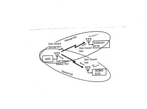
Source: Reprinted from Figure 4-3 courtesy of (Adamy D. L., Space Electronic Warfare, 2021)
When a communication signal is jammed or spoofed, there is a link from the desired transmitter to the receiver and a link from a jammer or spoofer to the receiver. (Adamy D. L., Space Electronic Warfare, 2021) [14] Refer to 3-X
Figure 3-31 Jammed / Spoofed Communications Signal
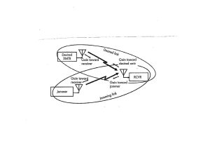
Source: Reprinted from Figure 4-4 courtesy of (Adamy D. L., Space Electronic Warfare, 2021)
Propagation Loss Models
(Adamy D. L., Space Electronic Warfare, 2021) presents several propagation loss models within the atmosphere based on a clear or obstructed path and Fresnel zone distance. Refer to Table 3- These models are LOS (free space loss or spreading loss), two-ray propagation for phase cancellation, and KED (knife-edge loss). Adamy also considers atmospheric, rain, and fog losses.
Table 3-4 Selection of Appropriate Propagation Loss Model
| Clear propagation path | Low frequency, wide beams near the ground | Link longer than Fresnel-zone distance | Use two-ray model |
| Link shorter than Fresnel-zone distance | Use LOS model | ||
| Hight-frequency, narrow-beams | Far from ground | Use LOS model | |
| Propagation path obstructed by terrain. | Calculate additional loss from the KED model |
Source: Reprinted from Table 4.1 courtesy of (Adamy D. L., Space Electronic Warfare, 2021)
When radio transmission and propagation is to or from an Earth satellite, there are special considerations due to the nature of space, losses due to extreme long range, and the geometry of the links. The formula gives the received power at the receiver:
[latex]P_R = ERP-L + G_R[/latex] Eq. 3-18
Where:
[latex]P_R[/latex]– received signal power in dBm
[latex]ERP[/latex]– the effective radiated power, in dBm
[latex]L[/latex] – losses from all causes between transmitting and receiving antennas in dBm
[latex]G_R[/latex]– receiver antenna gain in dBm
The total path loss to or from a satellite includes LOS loss, atmospheric loss, antenna misalignment loss, polarization loss, and rain loss. (Adamy D. L., Space Electronic Warfare, 2021) [15]
Satellite Links
Satellites are, by nature, remote from the ground and must be connected by links. Uplink and downlink geometry is a complex set of calculations related to satellite position, North Pole, longitudes, latitudes, sub-vehicle points (SVP), Center of Earth, ground station, Equator, Greenwich Meridian, Azimuth to the ground station, satellite movement in the horizontal plane, satellite payloads, radar bore sights, and hostile target detection, all wrapped up in complex orbital and spherical geometry calculations. (Adamy D. L., Space Electronic Warfare, 2021) spends four challenging chapters on this subject. We will assume that Keplerian ephemeris, Napier’s rules, and the Laws of Sines, Cosines for sides and angles haven’t been overruled by Executive Order (EO), which leads us to a discussion of Link vulnerability to EW. [16]
Link Vulnerability to EW: Space-Related Losses, Intercept (Jamming) & Spoofing
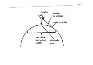
Satellites are from Earth but present excellent loss of signal (LOS) from a large part of the Earth’s surface. They are highly susceptible to three kinds of hostile activity. Signals from satellites can be intercepted, and strong hostile transmissions can be jamming signals, interfering with uplink or downlink signals to prevent proper reception. They can also be spoofing signals that cause the satellite to interpret them as functional commands that are harmful or transmit useless positional data. (Adamy D. L., Space Electronic Warfare, 2021) This section and the following will focus heavily on spoofing and the downlink interpretation of false signals in GNSS/GPS/ADS-B receivers.
Figure 3-32 shows a successful intercept of a satellite signal. Successful intercept gives the hostile receiver a high-quality signal to recover important information. A ground-based jammer operating against a satellite uplink transmits to the link receiver in the satellite. The ground station and the jammer must be above the horizon from the satellite. The received signals are intended for the receiver in the satellite control station (GCS) or other authorized receiver. There is a separate link to any hostile receiver. (Adamy D. L., EW 103: Tactical Battlefield Communications Electronic Warfare, 2009) (Adamy D. L., Space Electronic Warfare, 2021)
Successful spoofing places a strong enough signal into a satellite link receiver to cause the satellite or its payload to accept it as a valid command. Command spoofing could cause the satellite to perform a maneuver that ends the mission or put the payload in an unusable state. (Adamy D. L., Space Electronic Warfare, 2021)
Figure 3-33 shows a successful spoofing of a satellite signal. A ground-based spoofer operating against a satellite uplink transmits to the link receiver in the satellite. The ground station and the jammer must be above the horizon from the satellite.[17]
Figure 3-32 Intercept
Source: Figure 3-32 Modified from Figure 7.1 Courtesy of (Adamy D. L., Space Electronic Warfare, 2021)
Figure 3-33 Spoofing
Source: Figure 3-33 Modified from Figure 7.2 Courtesy of (Adamy D. L., Space Electronic Warfare, 2021)
Space-Related Link Losses
Any attack on a satellite link may involve single or multiple links. Each link is subject to transmission losses, including LOS, atmospheric, antenna misalignment, rain, and polarization losses.
An intercept link is separate from the intended command and data links. It goes from the satellite’s link transmitter (onboard or at GCS) to a hostile receiver. The quality of the intercept is judged by the Signal to Noise (S/N) ratio achieved in the hostile receiver. (Adamy D. L., Space Electronic Warfare, 2021)
A spoofing link goes from the hostile transmitter to a satellite link receiver. This receiver is generally on the satellite. The spoofing signal’s purpose is to cause it to function improperly, but if the spoofer is in the GCS, the purpose is to invalidate the date – especially localization data. (Adamy D. L., EW 104: EW against a new generation of threats, 2015)
Jamming of any satellite link is communications jamming. Jamming effectiveness is defined in terms of the Jamming-to-Signal ratio (J/S) that it causes. It is calculated from the following formula:
[latex]{J/S}=ERP_J-ERP_S-LOSS_J+LOSS_S+G_{RJ}-G_R[/latex] EQ. 3-19
Where:
[latex]{J / S}[/latex]= jamming-to-signal ratio in decibels
[latex]ERP_J[/latex] = effective radiated power (ERP) of jamming transmitter toward the target receiver in dBm
[latex]ERP_S[/latex] = ERP of the desired signal toward the receiver in dBm
[latex]LOSS_J[/latex] = transmission loss from the jammer to target a receiver in dBm
[latex]LOSS_S[/latex] = transmission loss from transmitter to target a receiver in decibels
[latex]G_{RJ}[/latex] = gain of receiving antenna in the direction of a jammer in decibels
[latex]G_R[/latex] = gain of receiving antenna toward transmitter in decibels
The last two terms cancel each other if the target receiver has a non-directional antenna.
(Adamy D. L., Space Electronic Warfare, 2021) in his textbook, he presents and solves detailed examples of intercepting, jamming, and spoofing uplinks and downlinks. [18]
We now discuss spoofing in detail and its implications concerning navigation and location services. We will focus on a particularly promising anti-spoofing technology known as ECD.
GPS/GNSS/ADS-B SPOOFING
Two issues are discussed: 1) GPS spoofing detection and mitigation for GNSS / GPS using the ECD algorithm, and 2) GPS spoofing of ADS-B systems.[19] Recognize that ADS-B is a subset of the larger receiver localization problem. Solutions that apply to the larger vector space, GNSS / GPS, also are valid for the subset, ADS-B, if computational hardware is available. GPS spoofing is a reasonably well-researched topic. Many methods have been proposed to detect and mitigate spoofing. The lion’s share of the research focuses on detecting spoofing attacks. Methods of spoofing mitigation are often specialized or computational burdensome. Civilian COTS anti-spoofing countermeasures are rare. But a much better technology is available to Detect, Mitigate and Recover Spoofed satellite signals – even those with a precursor Jamming attack. It is called ECD.
ECD: EICHELBERGER COLLECTIVE DETECTION
This section covers the brilliant value-added research by Dr. Manuel Eichelberger on the detection, mitigation, and recovery of GPS spoofed signals. (Eichelberger, Robust Global Localization using GPS and Aircraft Signals, 2019) ECD implementation and evaluation show that with some modifications, the robustness of collective detection (CD) can be exploited to mitigate spoofing attacks. (Eichelberger, Robust Global Localization using GPS and Aircraft Signals, 2019) shows that multiple locations, including the actual one, can be recovered from scenarios where several signals are present. [20] [21]
ECD does not track signals. It works with signal snapshots. It is suitable for snapshot receivers, a new low-power GPS receiver class. (M.Eichelberger, 2019) (J.Liu & et.al., 2012)
ADS-B’s high dependency on communication and navigation (GNSS) systems causes the system to inherit the vulnerabilities of those systems. This results in more opportunities (threats) to exploit those vulnerabilities. In general, advancements in computers, connectivity, storage, hardware, software, and apps are major aids to malicious parties who wish to carry out spoofing and other threats by exploiting the vulnerabilities of ADS-B. Another main vulnerability of ADS-B systems is their broadcast nature without security measures, which can easily be exploited to cause harm.
Qualitative Risk Assessment Opinion based on FAA SRM Reference Guidelines (FAA, 2018) (FAA, 2021) (FAA, 2019)
After reviewing data, papers, and reports regarding the Severity, Likelihood, and Risks associated with spoofing GNSS/ GPS signals, there are two schools of thought. Before 2015, transmitting fake GNSS/GPS signals was a qualitative – unlikely [Table 3-C Remote] (FAA, 2018) risk and a niche issue. After 2015, the world changed considerably. Low-cost SDR RF signal generators combined with an awareness that spoofing was a powerful disruption technique and availability of COTs precipitated a sharp increase in incidents ranging from amateur to researcher generated to professional crook to the nation-state. The Ling and Qing demonstration of the SDR signal spoofer at DEFCON 2015 plus the 2013 spoofing of the 213′ motor yacht White Rose of Drach’s by Humphreys’ team set the stage for significant spoofing incidents to follow. (T.E. Humphrees, 2008)
Two organizations report the spoofing risks quite differently. These are the FAA and US Navy. The FAA is concerned with aircraft and UAS. It considers the severity of signal spoofing threat to be Major [Table 2 -3] (FAA, 2018) because of substantial damage to the aircraft vehicle and physical distress or injuries to persons without loss of life. Depending on circumstances, FAA sees the Likelihood as Probable – especially for UAS. [Table 4-B]. (FAA, 2018) The US Navy sees the spoofing threat quite differently. It considered the spate of incidents in 2016 in Moscow, the Black Sea in 2017, the Port of Shanghai in 2019, and the loss of 20 sailors in the South China Seas in 2017 involving incidents with the USS McCain and USS Fitzgerald colliding with commercial vessels Alnic MC and ACX. The US Navy sees the spoofing severity as Catastrophic [Table 2-1] because of multiple fatalities, loss, and/or severe damage to ships and defensive aircraft. Further, the US Navy’s view appears to be that the Likelihood is Probable [Table 3-B]. (FAA, 2018) Depending on the view, spoofing can be considered at Risk Levels Yellow or Red [Medium to High], i.e., medium acceptable risk to unacceptable risk. This is based on the number of researchers and analysts studying / reporting/conventions on GNSS/GPS spoofing countermeasures since 2018.
Using FAA SRM Guidelines, signal spoofing on UAS /ADS-B systems is above average likelihood (probable -> frequent) and severe [Yellow bordering on Red or in terms of the severity qualitative scale three -> 2 ]. (FAA, 2019)
Risk Assessment Spoofing Classes
Risk Assessment for spoofing threats into four classifications: Part 107 Operations, BVLOS, Urban Areas, and Near Airports. Because of Federal guidelines and licensing requirements, Part 107 Operations specifies a near pristine Risk level or The Best-Case Scenario. Because the UAS is not limited to a specified space and may cross the visual horizon, BVLOS represents an elevated UAS spoofing threat and risk. Urban area operations represent a difficult case for spoofing with increased Severity of consequences—urban areas present difficulty in enacting countermeasure to a spoofing attack. Humans and equipment are at risk. Near Airports represents the Worst-Case scenario with the highest Severity and Likelihood Probability. There are globally reported UAS – aircraft and UAS – ship spoofing incidents that present serious consequences to human life. In all four classifications, spoofing is Probable. Both FAA and USN consider spoofing a real and escalating threat. It no longer represents a remote or niche possibility. (Kahn & M. Mohsin, 2021) (Nichols R. K., 2020) (M.L. Psiaki & Humphreys, 2016)
Dependence on GPS and vulnerability [22]
It is important to understand that both GPS (part of the GNSS family) and ADS-B systems are vulnerable to spoofing attacks on both manned and unmanned aircraft. In general, GPS vulnerabilities translate down to the more specific ADS-B subset, which has vulnerabilities in its own right. This report will detail the brilliant work of Dr. Michael Eichelberger on Robust Global Localization using GPS and Aircraft Signals. He describes a functional tool known as CD to detect, mitigate and counter spoofing (and jamming) attacks on all stages of GPS. (Eichelberger, Robust Global Localization using GPS and Aircraft Signals, 2019)
GPS is ubiquitous and incorporated into many applications (aircraft, ship, car /truck navigation; train routing and control; cellular network, stock market, and power grid synchronization) that make a “rich” target for spoofing a receiver’s perceived location or time. Wrong information in time or space can have severe consequences.
ATC is partially transitioning from radar to a scheme in which aircraft (A/C) transmit their current location twice per second through ADS-B messages. This system has been mandated in Europe and underway in the US since 2020. The A/C determines location using GPS. If the onboard GPS receiver estimates a wrong location due to spoofing, wrong routing instructions will be delivered due to a wrong reported A/C location, leading to an A/C crash.
Ships depend heavily on GPS. They have few reference points to localize themselves apart from GPS. Wrong location indication can strand a ship, cause a collision, push off course into dangerous waters, ground a ship, or turn a ship into a ghost or a missile. 2017 incidents in the Black Sea and South China Seas have been documented. (Burgess, 2017) (Nichols R. K.-P., 2019)
While planes and ships suffer spoofing attacks in the location domain, an attacker may also try to change the perceived time of a GPS receiver. Cellular networks rely on accurate time synchronization for exchanging communication data packets between ground antennas and mobile handsets in the same network cell. Also, all neighboring cells of the network need to be time synchronized for seamless call handoffs of handsets switching cells and coordinating data transmissions in overlapping coverage areas. Since most cellular ground stations get their timing information from GPS, a signal spoofing attacker could decouple cells from the common network time. Overlapping cells might send data simultaneously and frequencies, leading to message collisions and losses. (Anonymous, 2014) Failing communications networks can disrupt emergency services and businesses. (Eichelberger, Robust Global Localization using GPS and Aircraft Signals, 2019)
SPOOFING
Threats and weaknesses show that large damages (even fatal or catastrophic) can be caused by transmitting forged GPS signals. False signal generators may cost only a few hundred dollars of software and hardware.
A GPS receiver computing its location wrongly or even failing to estimate any location at all can have different causes. Wrong localization solutions come from 1) a low signal-to-noise ratio (SNR) of the signal (examples: inside a building or below trees in a canyon); 2) reflected signals in multipath scenarios, or 3) deliberately spoofed signals. (Eichelberger, Robust Global Localization using GPS and Aircraft Signals, 2019) discusses mitigating low SNR and multipath reflected signals. Signal spoofing (#3) is the most difficult case since the attacker can freely choose the signal power and delays for each satellite individually. (Eichelberger, Robust Global Localization using GPS and Aircraft Signals, 2019)
Before discussing ECD – Collective detection maximum likelihood localization approach (Eichelberger, Robust Global Localization using GPS and Aircraft Signals, 2019) it is best to step back and briefly discuss GPS signals, classical GPS receivers, A-GPS, and snapshot receivers. Then the ECD approach to spoofing will show some real power by comparison. Power is defined as both enhanced spoofing detection and mitigation capabilities. [23]
GPS SIGNAL
The GPS system consists of control, space, and user segments. The space segment contains the 24 orbiting satellites. The network monitor stations, GCS, and antennas comprise the control segment. The third and most important are the receivers, which comprise the user segment. (USGPO, 2021)
Satellites transmit signals in different frequency bands. These include the L1 and L2 frequency bands at 1.57542 GHz and 1.2276 GHz. (DoD, 2008) Signals from different satellites may be distinguished and extracted from background noise using code division multiple access protocols (CDMA). (DoD, 2008) Each satellite has a unique course/acquisition code (C/A) of 1023 bits. The C/A codes are PRN sequences transmitted at 10.23 MHz, which repeats every millisecond. The C /A code is merged using an XOR before being with the L1 or L2 carrier. The data broadcast has a timestamp called HOW, which is used to compute the location of the satellite when the packet was transmitted. The receiver needs accurate orbital information ( aka ephemeris) about the satellite, which changes over time. The timestamp is broadcast every six seconds; the ephemeris data can only be received if the receiver can decode at least 30 seconds of the signal.[24] (Eichelberger, Robust Global Localization using GPS and Aircraft Signals, 2019)
Classic Receivers
Classical GPS receivers use three stages when obtaining a location fix. They are Acquisition, Tracking, and localization.
Acquisition. The relative speed between satellite and receiver introduces a significant Doppler shift to the carrier frequency. [25] GPS receiver locates the set of available satellites. This is achieved by correlating the received signal with the satellites’. Since satellites move at considerable speeds. The signal frequency is affected by a Doppler shift. So, the receiver must correlate the received signal with C/ A codes with different Doppler shifts. (Eichelberger, Robust Global Localization using GPS and Aircraft Signals, 2019)
Tracking. After a set of satellites has been acquired, the data contained in the broadcast signal is decoded. Doppler shifts and C /A code phase are tracked using tracking loops. After the receiver obtains the ephemeris data and HOW timestamps from at least four satellites, it can start to compute its location. (Eichelberger, Robust Global Localization using GPS and Aircraft Signals, 2019)
Localization. Localization in GPS is achieved using signal time of flight (ToF) measurements. ToFs are the difference between the arrival times of the HOW timestamps decoded in the tracking stage of the receiver and those signal transmission timestamps themselves. [26] The local time at the receiver is unknown, and the localization is done using pseudo ranges. The receiver location is usually found using least-squares optimization. (Eichelberger, Robust Global Localization using GPS and Aircraft Signals, 2019) (Wikipedia, 2021)
A main disadvantage of GPS is the low bit rate of the navigation data encoded in the signals transmitted by the satellites. The minimal data necessary to compute a location fix, which includes the ephemerides of the satellites, repeats only every 30 seconds. [27]
A-GPS (Assisted GPS) – Reducing the Start-Up Time
Assisted GPS (A-GPS) drastically reduces the start-up time by fetching the navigation data over the Internet, commonly by connecting via a cellular network. Data transmission over cellular networks is faster than decoding GPS signals and normally only takes a few seconds. The ephemeris data is valid for 30 minutes. The acquisition time can be reduced using that data since the available satellites can be estimated along with their expected Doppler shifts. With A-GPS, the receiver still needs to extract the HOW timestamps from the signal. However, these timestamps are transmitted every six seconds, which translates to how long it takes the A-GPS receiver to compute a location fix. (Eichelberger, Robust Global Localization using GPS and Aircraft Signals, 2019)
Course-Time Navigation
Course-Time Navigation (CTN) is an A-GPS technique that drops the requirement to decode the HOW timestamps from the GPS signals. (Diggelen, 2009) The only information from the GPS signals is the phases of the C/A code sequences detected by a matched filter. Those C/A code arrival times are directly related to the sub-milliseconds unambiguously; the deviation may be no more than 150 km from the correct values. [28] [29] Since the PRN sequences repeat every millisecond, without considering navigation data flips in the signal, CTN can, in theory, compute a location from one millisecond of the sampled signal. [30] Noise can be an issue with such short signal recordings because it cannot be filtered out the same way with longer recordings of several seconds. The big advantage is that signal processing is fast and power-efficient and reduces the latency of the first fix. Since no metadata is extracted from the GPS signal, CTN can often compute a location even in the presence of noise or attenuation. (Diggelen, 2009)
Snapshot Receivers
Snapshot receivers aim at the remaining latency that results from the transmission of timestamps from satellites every six seconds. Snapshot receivers can determine the ranges to the satellite modulo 1 ms, which corresponds to 300 km.
COLLECTIVE DETECTION
Collective Detection (CD) is a maximum likelihood snapshot receiver localization method, which does not determine the arrival time for each satellite but combines all the available information and decides only at the end of the computation. [31] This technique is critical to the (Eichelberger, Robust Global Localization using GPS and Aircraft Signals, 2019) invention to mitigate spoofing attacks on GPS or ADS-B. CD can tolerate a few low-quality satellite signals and is more robust than CTN. CD requires a lot of computational power. CD can be sped up by a branch and bound approach, which reduces the computational power per location fix to the order of one second even for uncertainties of 100 km and a minute. CD improvements and research has been plentiful. (Eichelberger, Robust Global Localization using GPS and Aircraft Signals, 2019) (J.Liu & et.al., 2012) (Axelrod & al, 2011) (P. Bissag, 2017)
ECD
Returning to the spoofing attack discussion, Dr. Manuel Eichelberger’s CD – Collective detection maximum likelihood localization approach method not only can detect spoofing attacks but also mitigate them! The ECD approach is a robust algorithm to mitigate spoofing. ECD can differentiate closer differences between the correct and spoofed locations than previously known approaches. (Eichelberger, Robust Global Localization using GPS and Aircraft Signals, 2019) COTS has little spoofing integrated defenses. Military receivers use symmetrically encrypted GPS signals, subject to a “replay” attack with a small delay to confuse receivers.
ECD solves even the toughest type of GPS spoofing attack consisting of spoofed signals with power levels similar to the authentic ones. (Eichelberger, Robust Global Localization using GPS and Aircraft Signals, 2019) ECD achieves median errors under 19 m on the TEXBAT dataset, which is the de facto reference dataset for testing GPS anti-spoofing algorithms. (Ranganathan & al., 2016) (Wesson, 2014) The ECD approach uses only a few milliseconds of raw GPS signals, so-called snapshots, for each location fix. This enables offloading of the computation into the Cloud, which allows knowledge of observed attacks. [32] Existing spoofing mitigation methods require a constant stream of GPS signals and tracking those signals over time. Computational load increases because fake signals must be detected, removed, or bypassed. (Eichelberger, Robust Global Localization using GPS and Aircraft Signals, 2019)
Research to 2016: Survey of Effective GPS Spoofing Countermeasures
Because of the overwhelming dependence on GPS in every sector, ranging from civilian to military, researchers have been trying desperately to find a complete solution to the spoofing threat. To understand that ECD ( following sections) is a brilliant departure from past efforts, it is necessary to briefly cover the prevailing common wisdom. Haider and Khalid 2016 published an adequate survey of spoofing countermeasures up through the end of 2016. (Haider & Khalid, 2016)
Spoofing Techniques
According to (Haider & Khalid, 2016) there are three common GPS Spoofing techniques with different sophistication levels. They are simplistic, intermediate, and sophisticated. (Humphreys & al., 2008)
The simplistic spoofing attack is the most commonly used technique to spoof GPS receivers. It only requires a COTS GPS signal simulator, amplifier, and antenna to broadcast signals towards the GPS receiver. It was performed successfully by Los Almos National Laboratory in 2002. (Warner & Johnson, 2002) Simplistic spoofing attacks can be expensive as the GPS simulator can run $400K and is heavy (not mobile). The available GPS signal and detection do not synchronize simulator signals is easy.
In the intermediate spoofing attack, the spoofing component consists of a GPS receiver to receiver a genuine GPS signal and a spoofing device to transmit a fake GPS signal. The idea is to estimate the target receiver antenna position and velocity and then broadcast a fake signal relative to the genuine GPS signal. This type of spoofing attack is difficult to detect and can be partially prevented using an IMU. (Humphreys & al., 2008)
In sophisticated spoofing attacks, multiple receiver-spoofer devices target the GPS receiver from different angles and directions. In this scenario, the angle-of-attack defense against GPS spoofing in which the reception angle is monitored to detect spoofing fails. The only known defense successful against such an attack is cryptographic authentication. (Humphreys & al., 2008) [33]
Note that prior research on spoofing was to exclude the fake signals and focus on a single satellite. ECD ( next section) includes the fake signal on a minimum of four satellites and then progressively / selectively eliminates their effect until the real weaker GPS signals become apparent. (Eichelberger, Robust Global Localization using GPS and Aircraft Signals, 2019)
(Haider & Khalid, 2016), present findings based on six innovative research papers that cover spoofing countermeasures. These are:
- Multi-test Detection and Protection Algorithm against Spoofing Attacks on GNSS Receivers (Jovanovic & Botteron, 2014)
- GPS Spoofing Countermeasures (Warner & Johnston, 2003)
- An Asymmetric Security Mechanism for Navigation Signals (Kuhn, 2015)
- A Cross-layer defense mechanism against GPS spoofing attacks on PMUs in Smart Grid (Fan & al., 2015)
- Detection and Mitigation of GPS Spoofing Based on Antenna Array Processing (Magiera & Katulski, 2015)
- GPS Spoofing Detection via Dual-Receiver Correlation of Military Signals(Psiaki & al., 2013)
A-F Analysis (Haider & Khalid, 2016)
(Haider & Khalid, 2016) present two tables that show the criteria used to evaluate each technique to find the most effective GPS spoofing CM and present the analysis of A-F with specific criteria. From their tables, we can discern that almost all the techniques can offer protection against a simplistic spoofing attack (Kuhn, 2015) (Jovanovic & Botteron, 2014) (Fan & al., 2015) (Magiera & Katulski, 2015) (Psiaki & al., 2013). Only two techniques can protect against sophisticated attacks (Kuhn, 2015) (Psiaki & al., 2013). This represents a reasonable look at the state-of-the-art GPS spoofing CMs in 2016.
Then along comes Dr. Manuel Eichelberger and ECD!
GPS Spoofing Research: Out-of-the-Box Brilliance to ECD Defense
Three research tracks are most relevant to ECD / CD: Maximum Likelihood Localization, Spoofing Mitigation algorithms, and Successive Signal Interference Cancellation (SIC). Historical spoofing research focuses primarily on the detection of singular SPS source attacks. ECD’s hallmark is to focus on mitigation, correction, and recovery attending to multiple spoofing signals on multiple satellite attack surfaces.
Maximum Likelihood Localization
CD is a maximum likelihood GPS localization technique. It was proposed in 1996 but considered computationally infeasible at that time. (Spilker, 1996) CD was first implemented by Axelrad et al. in 2011. (Axelrod & al, 2011) The search space contained millions or more location hypotheses. Improvements in the computational burden were found using various heuristics. (Cheong & al., 2011) (Jia, 2016) A breakthrough came with the proposal of a branch-and-bound algorithm that finds the optimal solution within ten seconds running on a single CPU thread. (P. Bissag, 2017)
Spoofing Mitigation
GPS spoofing defenses have intensively been studied. Most of them focus on detecting spoofing attacks. There is a paucity of prior research for spoofing mitigation and recovering from successful attacks by finding and authenticating the correct signals. (M.L. Psiaki & Humphreys, 2016) In contrast to the vast research on GPS spoofing, there is a lack of commercial, civil receivers with anti-spoofing capabilities. (Eichelberger, Robust Global Localization using GPS and Aircraft Signals, 2019) ECD inherently mitigates spoofing attacks. The tide will turn.[34]
Spoofing hardware performing a sophisticated, seamless satellite-lock takeover attack has been built. (Humphreys & al., 2008) Challenges associated with spoofing are matching the spoofed and authentic signals ‘ amplitudes at the receiver, which might not be in LOS and moving. (Schmidt & al, 2016)
It is practically feasible for a spoofer to erase the authentic signals at a 180-degree phase offset. (M.L. Psiaki & Humphreys, 2016) This is one of the strongest attacks that can only be detected with multiple receiver antennas or by a moving receiver. (M.L. Psiaki & Humphreys, 2016) For signal erasure to be feasible, the spoofer needs to know the receiver location more accurately than the GPS L1 wavelength, which is 19 cm. Receivers with only a single antenna cannot withstand such an erasure attack. ECD targets single-antenna receivers and does not deal with signal erasure. (Eichelberger, Robust Global Localization using GPS and Aircraft Signals, 2019) In all other types of spoofing attacks, including signal replay and multiple transmission antenna implementations, the original signals are still present, and ECD remains robust. (Eichelberger, Robust Global Localization using GPS and Aircraft Signals, 2019) Detecting multi-antenna receivers and differentiating signal timing consistencies are covered in (Tippenhauer & et.al, 2011)
The GPS anti-spoofing work most relevant to ECD is based on the joint processing of satellite signals and the maximum likelihood of localization. One method can mitigate a limited number of spoofed signals by vector tracking of all satellite signals. (Jafarnia-Jahromi & al., 2012) A similar technique is shown to be robust against jamming and signal replay. (Y. Ng & Gao, 2016)
Successive Signal Interference Cancellation [35]
ECD uses an iterative signal damping technique with spoofing signals similar to SIC. SIC removes the strongest received signals one by one to find the weaker ones that have been used with GPS signals before. (G. Lopez-Risueno & Seco-Granados, 2005) (Madhani & al., 2003) That work is based on a classical receiver architecture which only keeps a signal’s timing, amplitude, and phase. The ECD has its snapshot receiver based on CD, which directly operates in the localization domain and does not identify individual signals in an intermediate stage. It is impossible to differentiate between authentic and spoofed signals, a priori, ECD does not remove signals from the sample data. Otherwise. The localization algorithm might lose the information from authentic signals/ Instead, ECD dampens strong signals by 60% to reveal weaker signals. This can reveal localization solutions with lower CD likelihood. (Eichelberger, Robust Global Localization using GPS and Aircraft Signals, 2019)
GPS Signal Jamming
The easiest way to prevent a receiver from finding a GPS location is by jamming the GPS frequency band. GPS signals are weak and require sophisticated processing to be found. Satellite signal jamming considerably worsens the signal-to-noise ratio (SNR) of the satellite signal acquisition results. ECD algorithms achieve a better SNR than classical receivers and can tolerate more noise or stronger jamming. (Eichelberger, Robust Global Localization using GPS and Aircraft Signals, 2019)
A jammed receiver is less likely to detect spoofing since the original signals cannot be accurately determined. The receiver tries to acquire any satellite signals it can find. The attacker only needs to send a set of valid GPS satellite signals stronger than the noise floor without synchronizing with the authentic signals. [36] (Eichelberger, Robust Global Localization using GPS and Aircraft Signals, 2019)
There is a more powerful and subtle attack on the jammed signal. The spoofer can send a set of satellite signals with adjusted power levels and synchronized to the authentic signals to successfully spoof the receiver. (Eichelberger, Robust Global Localization using GPS and Aircraft Signals, 2019) So even if the receiver has countermeasures to differentiate the jamming, the spoofer signals will be accepted as authentic. (Nichols R. K., 2020)
Two Robust GPS Signal Spoofing Attacks and ECD
Two of the most powerful GPS signal spoofing attacks are Seamless Satellite-Lock Takeover (SSLT) and Navigation Data Modification (NDM). How does ECD perform against these?
Seamless Satellite-Lock Takeover (SSLT)
The most powerful attack is a seamless satellite-lock takeover. In such an attack, the original and counterfeit signals are nearly identical concerning the satellite code, navigation data, code phase, transmission frequency, and received power. This requires the attacker to know the location of the spoofed device precisely so that ToF and power losses over a distance can be factored in. After matching the spoofed signals with the authentic ones, the spoofer can send its signals with a small power advantage to trick the receiver into tracking those instead of the authentic signals. A classical receiver without spoofing countermeasures, like tracking multiple peaks, cannot mitigate or detect the SSLT attack, and there is no indication of interruption of the receiver’s signal tracking. (Eichelberger, Robust Global Localization using GPS and Aircraft Signals, 2019)
Navigation Data Modification (NDM)
An attacker has two attack vectors: modifying the signal’s code phase or altering the navigation data—the former changes the signal arrival time measurements. The latter affects the perceived satellite locations. Both influence the calculated receiver location. ECD works with snapshot GPS receivers and is not vulnerable to NDM changes as they fetch information from other sources like the Internet. ECD deals with modified, wireless GPS signals.
ECD Algorithm Design
ECD is aimed at single-antenna receivers. Its spoofing mitigation algorithm object is to identify all likely localization solutions. It is based on CD because 1) CD has improved noise tolerance compared to classical receivers, 2) CD is suitable for snapshot receivers, 3) CD is not susceptible to navigation data modifications, and 4) CD computes a location likelihood distribution which can reveal all likely receiver locations including the actual location, independent of the number of spoofed and multipath signals. ECD avoids all the spoofing pitfalls and signal selection problems by joining and transforming all signals into a location likelihood distribution. Therefore, it defeats the top two GPS spoofing signal attacks. (Eichelberger, Robust Global Localization using GPS and Aircraft Signals, 2019)
Regarding the 4th point, Spoofing and multi-path signals are similar from a receiver’s perspective. Both result in several observed signals from the same satellite. The difference is that multipath signals have a delay dependent on the environment, while spoofing signals can be crafted to yield a consistent localization solution at the receiver. To detect spoofing and multipath signals, classical receivers can be modified to track an arbitrary number of signals per satellite instead of only one. (S.A.Shaukat & al., 2016) In such a receiver, the set of authentic signals – one signal from each satellite – would have to be correctly identified. Any selection of signals can be checked for consistency by verifying that the resulting residual error of the localization algorithm is very small. This is a combinatorically difficult problem. For n satellites and m transmitted sets of spoofed signals, there are (m+ 1) n possibilities for the receiver to select a set of signals. Only m + 1 of those will result in a consistent localization solution representing the actual location and m spoofed locations. ECD avoids this signal selection problem by joining and transforming all signals into a location likelihood distribution. (Eichelberger, Robust Global Localization using GPS and Aircraft Signals, 2019)
ECD only shows consistent signals since just a few overlapping (synced) signals for some location hypotheses do not accumulate a significant likelihood. All plausible receiver locations – given the observed signals – have a high likelihood. Finding these locations in four dimensions, space and time, is computationally expensive. (Bissig & Wattenhoffer, 2017)
Branch and Bound
Compared to exhaustively enumerating all the location hypotheses in the search space, a fast CD leveraging branch and bound algorithm is employed to reduce the computational load. (Eichelberger, Robust Global Localization using GPS and Aircraft Signals, 2019) describes the modifications to the B&B algorithm for ECD in copious detail in chapter 6. Eichelberger discusses acquisition, receiver implementation, and experiments using the TEXBAT database. [37] [38]
One of the key points under the receiver implementation concerns the correlation of C/A codes. [39]
The highest correlation is theoretically achieved when the C/A code in the received signal is aligned with the reference C/A code. Due to the pseudo-random nature of the C/A codes, a shift larger than one code chip from the correct location results in a low correlation value. Since one code chip has a duration of 1/1023 ms, the width of the peaks found in the acquisition vector is less than 2% of the total vector size. ECD reduces the maximum peak by 60% in each vector. A detection for partially overlapping peaks prevents changes to those peaks. Reducing the signal rather than eliminating it has a little negative impact on the accuracy. Before using these vectors in the next iteration of the algorithm, the acquisition result vectors are normalized again. This reduces the search space based on the prior iteration. (Eichelberger, Robust Global Localization using GPS and Aircraft Signals, 2019)
ADS-B Security
We next move into the subset problem, namely ADS-B systems on aircraft, both manned and unmanned. ADS-B ubiquitously uses GPS location and signal receiver technologies. ADS-B highly depends on communication and navigation (GNSS) systems. This is a fundamental cause of insecurity in the ADS-B system. It inherits the vulnerabilities of those systems and results in increased Risk and additional threats. (Nichols R. K., 2020) (Nichols R. K.-P., 2019)[40] Another vulnerability of the ADS-B system is its broadcast nature without security measures. These can easily be exploited to cause other threats such as eavesdropping on aircraft movement with the intention to harm, message deletion, and modification. The systems dependency on the onboard transponder is also considered a major vulnerability shared by the SSR. Aircraft hijackers can exploit this vulnerability to make the aircraft movements invisible. (Busyairah, 2019)
ADS-B Standards
ICAO has stressed including provisions for protecting critical information and communication technology systems against cyberattacks and interference, as stated in the Aviation Security Manual Document 8973/8. (ICAO, 2021) This was further emphasized in ATM Security Manual Document 9985 AN/492 to protect ATMs against cyberattacks. (ICAO, 2021)
ADS-B Security Requirements [41]
Strohmeier et al. (Strohmeier, 2015) and Nichols et al. (Nichols R. K.-P., 2019) have both outlined a set of security requirements for piloted aircraft and unmanned aircraft, respectively. Here are the combined security requirements for the ADS-B system in sync with the standard information security paradigm of the CIA:
- Data integrity [42]
The system security should ensure that ADS-B data received by the ground station or other aircraft (a/c) or UAS (if equipped) are the exact messages transmitted by the a/c. It should also be able to detect any malicious modification to the data during the broadcast.
- Source Integrity
The system security should verify that the ADS-B message received is sent by the actual owner ( correct a/c) of the message.
- Data origin (location / position fix) authentication
The system security should verify that the positioning information in the ADS-B message received is the original position of the a/c at the time of transmission.
- Low impact on current operations
The system security hardware/software should be compatible with the current ADS-B installation and standards.
- Sufficiently quick and correct detection of incidents
- Secure against DOS attacks against computing power
- System security functions need to be scalable irrespective of traffic density.
- Robustness to packet loss
Vulnerabilities in ADS-B system
Vulnerability in this section refers to the Ryan Nichols (RN) equations for information Risk determination. A vulnerability is a weakness in the system that makes it susceptible to exploitation via a threat or various types of threats. (Nichols R. K.-P., 2019) ADS-B system is vulnerable to security threats.
Broadcast Nature of RF Communications
ADS-B principle of operation, system components, integration, and operational environment are adequately discussed in Chapter 4 (Busyairah, 2019). The ADS-B system broadcasts ADS-B messages containing a/c state vector information and identity information via RF communication links such as 1090ES, UAT, or VDL Mode 4. The broadcast nature of the wireless networks without additional security measures is the main vulnerability in the system. (R.K. Nichols & Lekkas, 2002) [43]
No Cryptographic Mechanisms
The sender encrypts neither ADS-B messages at the point of origin nor the transmission links. There are no authentication mechanisms based on robust cryptographic security protocols. The ICAO (Airport’s authority of India 2014) has verified that no cryptographic mechanism is implemented in the ADS-B protocol. (Airports Authority of India, 2014) [44]
ADS-B COTS
ADS-B receivers are available in COTS at affordable prices. The receiver can track ADS-B capable a/c flying within a specific range of the receiver. The number of ADS-B tracking gadgets for all media is growing yearly. They can be used to hack the systems on UAS. (Nichols R. K.-P., 2019)
Shared Data
Due to the COTS availability of ADS-B receivers, private and public parties share real-time air traffic information on a/c on the Internet. Some websites on the internet provide digitized live ADS-B traffic data to the public, e.g., flightradar24.com, radarvirtuel.com, and FlightAware. The availability of the data and the capability to track individual a/c movements open the door to malicious parties to perform undesired acts that may have safety implications. (Busyairah, 2019)
Dependency On The On-Board Transponder
ADS-B encoding and broadcast are performed by either the transponder (for 1090ES) or an emitter (for UAT/ VDL Mode 4) on the a/c. Therefore, ADS-B aircraft surveillance is dependent on onboard equipment. There is a vulnerability (not cyber or spoofing) whereby the transponder or emitter can be turned off inside the cockpit. The a/c becomes invisible, and SSR and TCAS operation integrity is affected.
Complex System Architecture and Passthrough Of GNSS Vulnerabilities
ADS-B is an integrated system, dependent on an on-board navigation system to obtain information about the state of the a/c and a communication data link to broadcast the information to ATC on the ground and other ADS-B equipped a/c. The system interacts with external elements such as humans (controllers and pilots) and environmental factors. The integrated nature of the system increases the vulnerability of the system. The system inherits the vulnerabilities of the GNSS on which the system relies to obtain a/c positioning information! The ADS-B system also inherits vulnerabilities of the communications links. (Busyairah, 2019) (Eichelberger, Robust Global Localization using GPS and Aircraft Signals, 2019) (The Royal Academy of Engineering, 2011)
Threats to ADS-B system
Threats in this section refer to the Ryan Nichols (RN) equations for information Risk determination. A Threat is an action exploiting a vulnerability in the system to cause damage or harm specifically to a/c and generally to the Air Traffic Services (ATS), intentionally or unintentionally. (Nichols R. K.-P., 2019) ADS-B system is vulnerable to security threats.
Eavesdropping
The broadcast nature of ADS-B RF communication links without additional security measures (cryptographic mechanisms) enables the act of eavesdropping on the transmission. Eavesdropping can lead to serious threats such as targeting specific a/c movement information with the intention to harm the a/c. This can be done with more sophisticated traffic and signal analysis using available sources such as Mode S and ASDS-B capable open-source GNU Radio modules or SDR. Eavesdropping is a violation of confidentiality and compromises system security. (Busyairah, 2019)
Data-Link Jamming
Data-link jamming is an act of deliberate / non-deliberate blocking, jamming, or causing interference in wireless communications. (R.K. Nichols & Lekkas, 2002) Deliberate jamming using a radio jammer device aims to disrupt information flow ( message sending /receiving) between users within a wireless network. Jammer devices can be easily obtained as COTS devices. (Strohmeier, 2015) (R.K. Nichols & Lekkas, 2002) Using the Ryan Nichols equations, the Impact is severe in aviation due to the large coverage area (airspace), which is impossible to control. It involves critical safety data; hence the computed Risk/lethality level is high. (R.K. Nichols & Lekkas, 2002) (Busyairah, 2019) The INFOSEC quality affected is availability because jamming stops the a/’c or ground stations or multiple users within a specific area from communicating. On Air Traffic Control
Jamming is performed on ADS-B frequencies, e.g., 1090MHz. The targeted jamming attack would disable ATS at any airport using ATCC. Jamming a moving a/c is difficult but feasible. (Strohmeier, 2015)
ADS-B system transmitting on 1090ES is prone to unintentional signal jamming due to the use of the same frequency (Mode S 1090 MHz) by many systems such as SSR, TCAS, MLAT, and ADS-B, particularly in dense space. (Busyairah, 2019) [45] Not only is ADS-B prone to jamming, but so is SSR. (Adamy D. , EW 101: A First Course in Electronic Warfare, 2001)[46]
Two Types of Jamming Threats for ADS-B
Apart from GNSS (positioning source for ADS-B) jamming, the main jamming threats for the ADS-B system include GS Flood Denial and A/C Flood Denial.
Ground Station Flood Denial (GSFD)
The GSFD blocks 1090 MHz transmissions at the ADS-B ground station. There is no difficulty in gaining close proximity to a ground station. Jamming can be performed using a low-power jamming device to block ADS-B signals from A/C to the ground station. The threat does not target individual a/c. It blocks ADS-B signals from all A/C within the range of the ground station.
Aircraft Flood Denial (A/C FD)
A/CFD blocks signal transmission to the a/c. This threat disables the reception of ADS-B IN messages, TCAS, and WAM/MLAT and SSR interrogation. It is very difficult to gain close proximity to a moving A/C. The attacker needs to use a high-powered jamming device. According to (D. McCallie, 2011) these devices are not easy to obtain. MAYBE (see author note).[47] The jamming function will be ineffective as soon as the a/c moves out of the specific range of the jamming device. Better attempts can be made from within the a/c. [48]
ADS-B Signal Spoofing
ADS-B signal spoofing attempts to deceive an ADS-B receiver by broadcasting fake ADS-B signals structured to resemble a set of normal ADS-B signals or by re-broadcasting genuine signals captured elsewhere or at a different time. Spoofing an ADS-B system is also known as message injection because fake (ghost) a/c is introduced into the air traffic. The system’s vulnerability – having no authentication measures implemented at the systems data link layer – enables this threat. Spoofing is a hit on the security goal of Integrity. This leads to undesired operational decisions by controllers or surveillance operations in the air or on the ground. The threat affects both ADS-B IN and OUT systems. (Busyairah, 2019) Spoofing threats are of two basic varieties: Ground Station Target Ghost Injection / Flooding and Ground Station Target Ghost Injection / Flooding.
Ground Station Target Ghost Injection / Flooding
Ground Station Target Ghost Injection / Flooding is performed by injecting ADS-B signals from a single a/c or multiple fakes ( ghost) a/c into a ground station. This will cause single /multiple fake (ghost) a/c to appear on the controller’s working position (radar screen). [49]
Aircraft Target Ghost Injection / Flooding
Aircraft Target Ghost Injection / Flooding is performed by injecting ADS-B signals from a single a/c or multiple fake (ghost) a/c into an airplane in flight. This will cause ghost a/c to appear on the TCAS and CDTI screens in the cockpit to go haywire. Making the mess worse, the fake data will also be used by airborne operations such as ACAS, ATSAW, ITP, and others for aiding a/c navigation operations. (Busyairah, 2019)
ADS-B message Deletion
An a/c can be made to look like it has vanished from the ADS-B-based air traffic by deleting the ADS-B message broadcast from the a/c. This can be done by two methods: destructive interference and constructive interference. Destructive interference is performed by transmitting an inverse of an actual ADS-B signal to an ADS-B receiver. Constructive interference is performed by transmitting a duplicate of the ADS-B signal and adding the two signal waves ( original and duplicate). The two signal waves must be of the same frequency and phase and traveling in the same direction. Both approaches will result in being discarded by the ADS-B receiver as corrupt. (Busyairah, 2019)
ADS-B message modification
ADS-B message modification is feasible on the physical layer during transmission via datalinks using two methods: Signal Overshadowing and Bit-flipping. Signal overshadowing is done by sending a stronger signal to the ADS-B receiver, whereby only the stronger of the two colliding signals is received. This method will replace either the whole target message or part of it. Bit flipping is an algorithmic manipulation of bits. The attacker changes bits from 1 to 0 or vice versa. This will modify the ADS-B message and is a clear violation of the security goal of Integrity. (Strohmeier, 2015) This attack will disrupt ATC operations or a/c navigation.
HAPS
Of special interest to this reviewer is the possibility of using High Altitude UAS Platforms for wireless communications (HAPS) to replace the aircraft in retransmitting GPS signals and acting as the primary agent for indoor and outdoor localization procedures. Two important references detail the advantages and disadvantages of HAPS for communication systems and localization use. (Alejandro Aragon-Zavala, 2008) Nichols et al. provide an especially strong analysis of HAPS capabilities compared to terrestrial and satellite systems for telecommunications; HAPS platform advanced telecommunications services in various stages of engineering and development, HAPS link budgets, and characteristics of terrestrial, satellite, and haps systems. (Nichols R. K.-P., 2019)
Security of GNSS (Shrivastava, 2021) (Ochin & Lemieszewski, 2021)
In 2021 (Ochin & Lemieszewski, 2021) Ochin & Lemieszewski penned an excellent update on the spoofing threat covering air, land, and sea operations in Europe and Asia. Some interesting topics covered were self-spoofing or limpet spoofing technologies; DIY GNSS spoofers; [50] GNSS interference modalities; complementary countermeasures like INS; [51] GNSS jamming techniques; GNSS meaconing; and detailed sections on cloud-based GNSS positioning. Modern satellite navigation uses NO-Request range measurements between the navigation satellite and the user. The information about the satellite coordinates given to the user is included in the navigation signal. The way of range measurement is based on calculating the receiving signal time delay compared with the signals generated by the user’s equipment. (Ochin & Lemieszewski, 2021) Chapter 3 divides cloud-based spoofing detection into four classes and proceeds to mathematically define the antenna distances and navigation modes based on those classes. These detection modes are based on a single antenna spoofer and do not consider mitigation and recovery steps. This is compared to ECD, which does all three steps in the security solution.
Ochin & Lemieszewski (Ochin & Lemieszewski, 2021) present a fascinating picture of the history of anti-spoofing from 1942 patent to fight the American radio-controlled sea-based torpedoes with a radio jamming of German boats and submarines. (US Patent No. 2,292,387, 1942) They continue with a European view of security measures for the six satellite constellations. They conclude with a Postscript on the drama behind the taking by Iran of the US RQ-170 Sentinel and how they did it! (Goward, April 21, 2020) The Ochin & Lemieszewski chapter supports the risk opinions presented earlier. “The risk of losing GNSS signal (to spoofing) is growing daily. The accessories necessary for the manufacture of systems for GNSS “jamming” and “spoofing” are now widely available, and this type of attack can be taken advantage of by not only the military but also by terrorists.” (Ochin & Lemieszewski, 2021)
CONCLUSIONS
Space is the new frontier of electronic warfare (EW), intelligence, and reconnaissance. Signals are the soul of EMS. Space is also the place to view the earth in large “earth traces.” These views can help military and agricultural planners make better decisions on protecting the United States and managing (increase) global food supply, land usage, irrigation, and health. The same information for diametrically different uses. Chapter perused:
- Key definitions in EW, satellite systems, and ECD countermeasures
- A look at space calculations and satellite threats using plane and spherical trigonometry to explain orbital mechanics
- A brief review of EMS, signals, RADAR, Acoustic, and UAS Stealth principles,
- Signals to/from satellites and their vulnerabilities to Interception, Jamming, and Spoofing,
- The promising ECD technology countermeasure to spoofing can detect, mitigate, and recover fake and genuine signals. All ADS-B vulnerabilities and threats mentioned in Chapter 3 are amenable to ECD mitigation if sufficient computing horsepower is available.
Chapter 3 should prepare students for deeper dives into the fascinating world of space technologies.
References
Accuracy, G. G.-G. (2021, July 16). Official U.S. government information about the Global Positioning System (GPS) and related topics. Retrieved from https://www.gps.gov/: https://www.gps.gov/systems/gps/performance/accuracy/#problems
Adamy, D. -0. (2015). EW 104 EW against a New Generation of Threats. Boston: Artech House.
Adamy, D. (2001). EW 101 A First Course in Electronic Warfare. Boston, MA: Artech House.
Adamy, D. (2001). EW 101: A First Course in Electronic Warfare. Boston: Artech House.
Adamy, D. L. (2004). EW 102 ASecond Course in Electronic Warfare. Norwood, MA: Artech House.
Adamy, D. L. (2009). EW 103: Tactical Battlefield Communications Electronic Warfare. Norwood, MA: Artech House.
Adamy, D. L. (2015). EW 104: EW against a new generation of threats. Norwood, MA: Artech House.
Adamy, D. L. (2021). Space Electronic Warfare. Norwood, MA: Artech House.
Adamy, D.-9. (1998, Jan). Lesson 4: the basic link for all EW functions. (electronic warfare)(EW Reference & Source Guide). Journal of Electronic Defense, Jan 1998 Issue.
Airports Authority of India. (2014). Security Issues of ADS-B Operations. ICAO. Hong Kong, China: ICAO.
Alejandro Aragon-Zavala, J. L.-R.-P. (2008). High-Altitude Platforms for Wireless Communications. Chichester, West Sussex, UK: John Wiley & Sons.
Ali, e. a. (2014). ADS-B system failure modes and models. The Journal of Navigation, 67: 995-1017.
Anonymous. (2021, July 16). GPS newsgroup. Retrieved from http://gpsinformation.net/main/gpspower.htm: http://gpsinformation.net/main/gpspower.htm
Anonymous. (2014). Timing & Synchronization for LTE-TDD & LTE-Advanced Mobile Networks; Technical Report, Microsemi. Retrieved from www.microsemi.com: https://www.microsemi.com/document-portal/doc_download/133615-timing-sync-for-lte-tdd-lte-a-mobile-networks
Austin, R. (2010). “Design for Stealth,” Unmanned Aircraft Systems UAVS Design Development and Deployment. New York: John Wiley and Sons.
Axelrod, P., & al, e. (2011). Collective Detection and Direct Positioning Using Multiple GNSS Satellites. Navigation, pp. 58(4): 305-321.
Bissig, P., & Wattenhoffer, M. E. (2017). Fast & Robust GPS Fix using 1 millisecond of data. 16 ACM / IEEE Int Conf on Information Processing in Sensor Networks (pp. 223-234). Pittsburg, PA: IPSN.
Burch, D. (2015). RADAR for Mariners. New York: McGraw-Hill.
Burgess, M. (2017, September 21). When a Tanker Vanishes, all evidence points to Russia. Retrieved from https://www.wired.co.uk/: https://www.wired.co.uk/article/black-sea-ship-hacking-russia
Busyairah, S. A. (2019). Aircraft Surveillance Systems: Radar Limitations and the Advent of the Automatic Dependent Surveillance-Broadcast. New York: Routledge.
Cheong, J., & al., e. (2011). Efficient Implementation of Collective Detection. In IGNSS Symposium, 15-17.
Closas, P., & al., e. (2007). Maximum likelihood estimation of position in GNSS. IEEE Signal Processing Letters (pp. 14(5): 359-362). IEEE.
Cornell – LII. (2021, July 16). ADS-B law. Retrieved from https://www.law.cornell.edu/: https://www.law.cornell.edu/cfr/text/14/91.227#e
CYFO: A, M. (2018, Nov 4). CYFO Why Satellite Orbits Look Like Waves on Maps. Retrieved from https://www.youtube.com: https://www.youtube.com/watch?v=JyfEffMrglI
- McCallie, e. a. (2011). Security analysis of the ADS-B Implementation in the NEXT generation Air transport system. Inter J. of Critical Infrastructure Protection, 4: 78-87.
Data: USGS/NASA Landsat. (2021). Wipe-shows-water-loss-in-Lake-Mead-2000-2021.-Two-versions. Retrieved from https://stock.adobe.com/video/: https://stock.adobe.com/video/Wipe-shows-water-loss-in-Lake-Mead-2000-2021.-Two-versions.-Data%3A-USGS%2FNASA-/454218719?as_campaign=TinEye&as_content=tineye_match&epi1=454218719&tduid=3ccffe944195c552a79f6ba937c7a9c9&as_channel=affiliate&as_campclass=red
Diggelen, F. V. (2009). A-GPS: Assisted GPS, GNSS, and SBAS. NYC: Artech House.
DoD. (2008). Global Positioning System Performance Standard 4th edition (GPS SPS PS). Washington, DC: DoD.
Eichelberger, M. (2019). Robust Global Localization using GPS and Aircraft Signals. Zurich, Switzerland: Free Space Publishing, DISS. ETH No 26089.
Eichelberger, M., & Tanner, S. L. (2017). Indoor Localization with Aircraft Signals. ACM -Sen Sys -17, ISBN: 978-1-4503-5459-2.
EUROCONTROL. (2016, June). part_1_-_eurocontrol_specification_asterix_spec-149. Retrieved from https://www.eurocontrol.int/sites/: https://www.eurocontrol.int/sites/default/files/2019-06/part_1_-_eurocontrol_specification_asterix_spec-149_ed_2.4.pdf
FAA. (2018, April 27). FAA Safety Management. Retrieved from https://www.faa.gov/: https://www.faa.gov/regulations_policies/handbooks_manuals/aviation/risk_management/media/20180427_FAASRMGuidance5StepProcess_signed_508.pdf
FAA. (2019). ATO-SMS-Manual. Retrieved from https://www.faa.gov/: https://www.faa.gov/air_traffic/publications/media/ATO-SMS-Manual.pdf
FAA. (2021). SRM Safety Management Quick Reference Guide. Washington: FAA Manual Sections 3.5.4 & ff.
Fan, Y., & al., e. (2015). A Cross-layer defense mechanism against GPS spoofing attacks on PMUs in Smart Grid. IEEE Trans on Smart Grid, Vol 6. No. 6 November.
Fletcher, H. a. (1933). Loudness, its definition, measurement, and calculation. Journal of the Acoustical Society of America, 5, 82-108.
- Lopez-Risueno & Seco-Granados, G. (2005). Cn/sub 0/ estimation and near far mitigation for GNSS indoor receivers. In 2005 IEEE 61st Vehicular Technology Conf., V4: 2624-2628.
Global Security.Org. (2022, July 16). Chapter 3 Intelligence, Surveillance, and Reconnaissance Planning. Retrieved from https://www.globalsecurity.org/: https://www.globalsecurity.org/military/library/policy/army/fm/3-21-31/c03.htm
Goward, D. (April 21, 2020). GPS circle spoofing was discovered in Iran. GPS World.
GPSPATRON. (2022, July 9). GNSS Interference in wildlife. Retrieved from GPSPATRON.com: https://GPSPATRON.com/gnss-interference-from-wildlife/
Haider, Z., & Khalid, &. S. (2016). Survey of Effective GPS Spoofing Countermeasures. 6th Intern. Ann Conf on Innovative Computing Technology (INTECH 2016) (pp. 573-577). IEEE 978-1-5090-3/16.
Hubbard, R. K. (1998). Boater’s Bowditch. Camden, MA: International Marine.
Humphreys, T., & al., e. (2008). Assessing the spoofing threat: Development of a portable GPS civilian spoofer. In Radionavigation Laboratory Conf. Proc.
ICAO. (2021, June 2). atm_security_manual 9985. Retrieved from http://www.aviationchief.com/: http://www.aviationchief.com/uploads/9/2/0/9/92098238/icao_doc_9985_-_atm_security_manual_-_restricted_and_unedited_-_not_published_1.pdf
ICAO. (2021, June 2). Aviation Security Manual Document 8973/8. Retrieved from https://www.icao.int/Security/: https://www.icao.int/Security/SFP/Pages/SecurityManual.aspx
IS-GPS-200G. (2013, September 24). IS-GPS-200H, GLOBAL POSITIONING SYSTEMS DIRECTORATE SYSTEMS ENGINEERING & INTEGRATION: INTERFACE SPECIFICATION IS-GPS-200 – NAVSTAR GPS SPACE SEGMENT/NAVIGATION USER INTERFACES (24-SEP-2013). Retrieved from http://everyspec.com/: http://everyspec.com/MISC/IS-GPS-200H_53530/
ITU. (2019, July 19). ARTICLE 2 – Nomenclature – Section I – Frequency and Wavelength Bands. Retrieved from ITU Radio Communication Edition 2008: https://web.archive.org/web/20111001005059/http://life.itu.int/radioclub/rr/art02.htm
J.Liu, & et.al. (2012, November). Energy Efficient GPS Sensing with Cloud Offloading. Proceedings of 10 ACM Conference on Embedded Networked Sensor Signals (SenSys), pp. 85-89.
Jafarnia-Jahromi, A., & al., e. (2012). Detection and mitigation of spoofing attacks on a vector-based tracking GPS receiver. ION ITM.
Jia, Z. (2016). A Type of Collective Detection scheme with improved pigeon-inspired optimization. Inter. J. of Intelligent Computing and Cybernetics, 9(1):105-123.
Jovanovic, A., & Botteron, C. (2014). Multi-test Detection and Protection Algorithm against Spoofing Attacks on GNSS Receivers. PLANS IEEE/ION Position, Location and Navigation Symposium (pp. 5-8 May). Monterey, CA 5-8 May: IEEE/ION.
Kahn, S. Z., & M. Mohsin, &. W. (2021, May 7). On GPS spoofing of aerial platforms: a review of threats, challenges, methodologies, and future research directions. Comp Sci, p. 507 ff.
Kuhn, M. G. (2015). An Asymmetric Security Mechanism for Navigation Signals. 6th Info Hiding Workshop. Toronto, CA: Univ of Cambridge. Retrieved from https://www.cl.cam.ac.uk/~mgk25/ih2004-navsec.pdf
M.Eichelberger, v. H. (2019). Multi-year GPS tracking using a coin cell. In Proc. of 20th Inter.Workshop on Mobile Computing Systems & Applications ACM, 141-146.
M.L. Psiaki & Humphreys, T. (2016). GNSS Spoofing and Detection. Proc. of the IEEE, 104(6): 1258-1270.
Madhani, P., & al., e. (2003). Application of successive interference cancellation to the GPS pseudolite near-far problem. IEEE Trans, on Aerospace & Elect. Systems, 39(2):481-488.
Magiera, J., & Katulski, &. R. (2015). Detection and Mitigation of GPS Spoofing Based on Antenna Array Processing. J. of Applied Research & Technology, Vol 13. pp 45-47.
MIT R&D. (2022, July 16). ISR SYSTEMS AND TECHNOLOGY. Retrieved from https://www.ll.mit.edu/r-d/isr-systems-and-technology: https://www.ll.mit.edu/r-d/isr-systems-and-technology
Monahan, K. (2004). The Radar Book: Effective Navigation and Collision Avoidance. Anacortes, WA: Fineedge Publications.
Nichols, R. K. (2020). Counter Unmanned Aircraft Systems Technologies & Operations. Manhattan, KS: www.newprairiepress.org/ebooks/31.
Nichols, R. K., & Sincavage, S. M. (2022). DRONE DELIVERY OF CBNRECy – DEW WEAPONS Emerging Threats of Mini-Weapons of Mass Destruction and Disruption (WMDD). Manhattan, KS: New Prairie Press #46.
Nichols, R. K.-P. (2019). Unmanned Aircraft Systems in the Cyber Domain, 2nd Edition. Manhattan, KS: www.newprairiepress.org/ebooks/27.
Nichols, R., & al., e. (2020). Unmanned Vehicle Systems and Operations on Air, Sea, and Land. Manhattan, KS: New Prairie Press #35.
Ochin, E., & Lemieszewski, &. L. (2021). Chapter 3 Security of GNSS. In G. P. PETROPOULOS, & &. P. SRIVASTAVA, GPS and GNSS Technology in the Geosciences (pp. 51-73). NYC: Elsevier.
- Bissag, E. M. (2017, April). Fast and Robust GPS Fix Using One Millisecond of Data. Proc of the 16th ACM /IEEE International Conference on Information Processing in IPSN, pp. 223-234.
Psiaki, M., & al., e. (2013). GPS Spoofing Detection via Dual-Receiver Correlation of Military Signals. IEEE Tran of Aerospace & Electrical systems, vol 49, issue 4, pp. 2250-2260.
R.K. Nichols & Lekkas, P. (2002). Wireless Security; Threats, Models & Solutions. NYC: McGraw Hill.
R.K. Nichols, e. a. (2020). Unmanned Vehicle Systems & Operations on Air, Sea & Land. Manhattan, KS: New Prairie Press #35.
Ranganathan, A., & al., e. (2016). SPREE: A Spoofing Resistant GPS Receiver. Proc. of the 22nd ann Inter Conf. on Mobile Computing and Networking, ACM, pp. 348-360.
Ronfeldt, J. A. (1966). The Advent of Netwar. Santa Monica, CA: RAND.
Rosen, S. (2011). Signals and Systems for Speech and Hearing (2nd ed.). New York City: BRILL. p. 163.
S.A.Shaukat, & al., e. (2016). Robust vehicle localization with GPS dropouts. 6th ann Inter Conf on Intelligent and advanced systems (pp. 1-6). IEEE.
Schaefer, M., & Pearson, A. (2021). GPS and GNSS Technology in Geosciences. NYC: Elsevier.
Schmidt, D., & al, e. (2016). A Survey and Analysis of GNSS Spoofing Threat and Countermeasures. ACM Computing Surveys (CSUR), 48(4).
Shrivastava, G. P. (2021). GPS and GNSS Technology in the Geosciences. NYC: Elsevier.
Spilker, J. (1996). Fundamentals of Signal Tracking Theory. Prog in Astronautics & Aeronautics, 163:245-328.
Staff. (2016, April 17). Equal Loudness Contours. Retrieved from Gutenberg Organization: http://central.gutenberg.org/article/WHEBN0001046687/Equal-loudness%20contour
Strohmeier, M. (2015). On the security of the automatic dependent surveillance-broadcast protocol. IEEE Communications Surveys & Tutorials, 17:1066-1087.
A system, H. K. (1942). US Patent No. 2,292,387.
T.E. Humphrees, e. (2008). Assessing the Spoofing Threat: Development of a portable GPS Spoofing Civilian Spoofer. ION (pp. Sept 16-19). Savana, GA: ION.
The Royal Academy of Engineering. (2011). Global Navigation Space Systems: Reliance and Vulnerabilities. London: The Royal Academy of Engineering.
Tippenhauer, N., & et.al. (2011). On the requirements for successful spoofing attacks. Proc. of the 18th ACM Conf. on Computing and communications security (CCS), 75-86.
Toomay, J. (1982). RADAR for the Non – Specialist. London; Lifetime Learning Publications. London: Lifetime Learning Publications.
TRS, S. (2018, July 10). Tontechnic-Rechner-Sengpielaudio. Retrieved from Tontechnic-Rechner-Sengpielaudio Calculator: www.sengspielaudio.com/calculator-wavelength.htm
USGPO. (2020, April). Global Positioning System (GPS) Standard Positioning Service (SPS) 5th ed. Retrieved from https://www.gps.gov/technical/ps/: https://www.gps.gov/technical/ps/2020-SPS-performance-standard.pdf
USGPO. (2021, June 14). What is GPS? Retrieved from Gps.gov: www.gps.gov/sysytems/gps
Warner, J. S., & Johnston, R. (2003). GPS Spoofing Countermeasures. Journ of Security Administration. Retrieved from https://www.semanticscholar.org/paper/GPS-Spoofing-Countermeasures-Warner-Johnston/36e17f723bff8d429aca4714abe54500a9edaa49
Warner, J., & Johnson, &. R. (2002). A Simple Demonstration that the system (GPS) is vulnerable to spoofing. J. of Security Administration. Retrieved from https://the-eye.eu/public/Books/Electronic%20Archive/GPS-Spoofing-2002-2003.pdf
Weise, E. (2017, August 23). could-hackers-behind-u-s-navy-collisions. Retrieved from USATODAY: https://www.ruidosonews.com/story/tech/news/2017/08/23/could-hackers-behind-u-s-navy-collisions/594107001/
Wesson, K. (2014, May). Secure Navigation and Timing without Local Storage of Secret Keys. Ph.D. Thesis.
Wikipedia. (2021, June 2). Global Positioning System. Retrieved from https://en.wikipedia.org/wiki/: https://en.wikipedia.org/wiki/Global_Positioning_System
Wolff, C. (2022). Radar and Electronic Warfare Pocket Guide. Munich, Germany: Rhode & Schwarz.
- Ng & Gao, G. (2016). Mitigating jamming & meaconing attacks using direct GPS positioning. In Position, Location & Navigation Symposium (PLANS) IEEE/ION, 1021-1026.
Endnotes
[1] Definitions taken from (Eichelberger, Robust Global Localization using GPS and Aircraft Signals, 2019), (Wolff, 2022), (Nichols R. K.-P., 2019) and (Nichols & Sincavage, 2022)
[2] Since 1998, Christian Wolff has maintained the educational website www.radartutorial.eu
[3] ISR defined from the USA Army POV only.
[4] Ớ = Order of magnitude; dot = dot product for vectors
[5] All these systems are discussed in Chapter 2 of (Eichelberger, Robust Global Localization using GPS and Aircraft Signals, 2019)
[6] Each satellite has a unique 1023-bit PRN sequence, plus some current navigation data, D. Each bit is repeated 20 times for better robustness. Navigation data rate is limited to 50 bit / s. This also limits sending timestamps every 6 seconds, satellite orbit parameters (function of the satellite location over time) only every 30 seconds. As a result, the latency of the first location estimates after turning on a classic receiver, called the time to first fix (TTFF), can be high.
[7] Professor Adamy has about 50+ years of experience and as a SME has written an accelerated set of textbooks EW 101-104 to define the entire EW playing field. The author had the pleasure of studying under this accomplished researcher, practitioner, lecturer, and author.
[8] This chapter is a testament to (Adamy D. L., Space Electronic Warfare, 2021) work. It is impossible to summarize his experience and knowledge, so we have used sections of his technical teachings for our students.
[9] To multiply linear numbers, add their logarithms; to divide linear numbers, subtract their logarithms; to raise a linear number to the nth power, multiply its logarithm by n; and to take the nth root of a linear number, divide its logarithm by n.
[10] UAS and UAV are used synonymously. V=vehicle.
[11] Spoofing is added to the table by author based on his work with ECD and inferred from (Adamy D. L., EW 104: EW against a new generation of threats, 2015) , (Adamy D. L., Space Electronic Warfare, 2021) & (Nichols & Sincavage, 2022)
[12] Some useful factors: 1 Terahertz (THz) = 10**3 GHz = 10**6 MHz = 10 **12 Hz; and
1 nm = 10 (**-3) um (micron-meter) = 10 (**-6) mm (millimeter)= 10(**-9) m
1-micron, um = m / 1000000 (1 millionth of a meter).
[13] Adamy has written five stellar references on EW, use of dB logarithmic mathematics to solve EW equations for strength, gains, losses, radars, interceptors, jamming technologies, current threats, defense systems and more for the reader to research and enjoy. (Adamy D. -0., 2015)
[14] Spoofing affects the same path as a jammer.
[15] (Adamy D. L., Space Electronic Warfare, 2021) covers all these losses in nauseating detail. From a ChE POV (ye author) they are a just a total system loss regardless of root causes. One number. EEs and RADAR engineers will find this statement heresy.
[16] Author sarcasm.
[17] Spoofing is often accompanied by a precursive jamming operation. (Nichols R. K., 2020)
[18] There are important numbers for space EW calculations: A solar day is 24 hours or 1440 minutes. The sideral day is 23.9349 hours or 1436.094 minutes. Kepler’s third law is a3 = C x P2 where C= 36,355,285 km3 per min2 . Radius of earth is 6,371 km. The earth is proportionally a smooth sphere and can be assumed as a perfect sphere in orbital calculations. Synchronous satellite period is 23 hours and 56 minutes. The 12-hour satellite is 20,241 km high. Synchronous altitude is 35,873 km. Its range to the horizon is 41,348 km. The width of the earth from a synchronous satellite is 17.38 degrees. These all make excellent bar bets.
[19] Aircraft signal transfer is not the only means to localize indoor signals. HAPs, WiFi, Ultrasound, Light, Bluetooth, RFID. Sensor fusion and GSM all have a place in the decision-making process.
[20] Experiments based on the TEXBAT database show that a wide variety of attacks can be mitigated. In the TEXBAT scenarios, an attacker can introduce a maximum error of 222 m and a median error under 19 m. This is less than a sixth of the maximum unnoticed location offset reported in previous work that only detects spoofing attacks. (Ranganathan & al., 2016)
[21] According to SPSPATRON.com, GNSS Spoofing in Anti-Drone Systems is the most common application of GNSS spoofing. The anti-drone system simulates the coordinates of the nearest airport. The commercial drone is either landing or trying to fly to the takeoff point. There are different usage scenarios here. Sometimes only GPS is spoofed, and the other constellations are blocked. Sometimes GLONASS + GPS are spoofed. There are also different scenarios in terms of the duration of use. Automatic systems generate a fake signal within minutes. Sometimes a spoofer is activated for many hours. (GPSPATRON, 2022) ECD can handle this and other forms of signal spoofing.
[22] The author translated part of (Eichelberger, Robust Global Localization using GPS and Aircraft Signals, 2019) reference from the original German.
[23] The author has nicknamed Dr. Manuel Eichelberger’s brilliant doctorial research, ECD. ECD is Dr. Manuel Eichelberger’s advanced implementation of CD to detect and mitigate spoofing attacks on GPS or ADS-B signals
[24] This is a key point. CD reduces this timestamping process significantly.
[25] Data is sent on a carrier frequency of 1575.42 MHz (IS-GPS-200G, 2013)
[26] GPS satellites operate on atomic frequency standard, the receivers are not synchronized to GPS time.
[27] Because the receiver must decode all that data, it has to continuously track and process the satellite signals, which translates to high energy consumption. Furthermore, the TTFF on startup cost the user both latency and power.
[28] The deviation is defined as the time offset multiplied by the speed of light plus the location distance.
[29] For those who insist on SI / metric, 1 km = ~ 0.62 mi (miles)
[30] Data bit flips can happen. The normal practice is 2 milliseconds of sample time.
[31] The vector / tensor mathematics for localization are reasonably complex and can be found in Chapter 5.3 of (Eichelberger, Robust Global Localization using GPS and Aircraft Signals, 2019)
[32] Cloud offloading also makes ECD suitable for energy- constrained sensors.
[33] (Nichols & al., 2020) have argued the case for cryptographic authentication on civilian UAS /UUV and expanded the INFOSEC requirements.
[34] Author opinion.
[35] This is a key section to understanding the beauty of ECD. The entire SIC algorithm and ECD implications is found in detail in (Eichelberger, Robust Global Localization using GPS and Aircraft Signals, 2019) p81-ff.
[36] This is what makes jamming a lesser attack. The jamming is detectable by observing the noise floor, in-band power levels and loss of signal -lock takeover.
[37] See (Eichelberger, Robust Global Localization using GPS and Aircraft Signals, 2019) Sections 6.5 – 6.7 pages 84-94.
[38] See (Eichelberger, Robust Global Localization using GPS and Aircraft Signals, 2019) Sections 5.34 – 5.5 for extended discussions on space discretization, satellite visible set V, time discretization, averaging over likely hypotheses, hypothesis h, coding, efficient implementation of the B&B, local oscillator bias, criteria and test evaluations of ECD, computational considerations, and conclusions. (Closas & al., 2007)(J.Liu & et.al., 2012) (Diggelen, 2009)
[39] This is accomplished in the acquisition stage of a GPS receiver. The received signals is correlated with the C/A codes.
[40] (Nichols R. K., 2020) presents a model of Risk as a function of Threats, Vulnerabilities, Impact and Countermeasures known as the Ryan- Nichols equations, that models the qualitative effects of information flow through the communications and navigation systems in UAS.
[41] These INFOSEC goals are admirable but considering that most GPS and UAS COTS do not have sufficient GPS spoofing countermeasures or cybersecurity protections (most are legacy), the list is more of a wish list. [Author opinion]
[42] Please note the word “should.” Hackers just love this word.
[43] Wireless networks present few obstacles to access and can easily be attacked by open-source software. (R.K. Nichols, 2020)
[44] This is still true in legacy systems. Newer implementations have additional protections. UAS systems are notoriously weak in terms of security.
[45] Ali, et al. identified that jamming of GPS transmissions from the satellite affected the ADS-B system. (Ali, 2014)This is a rather obvious statement of research considering that we have also established that the vulnerabilities of GNSS/GPS pass down to ADS-B systems because they are subset of the larger problem.
[46] Dave Adamy is the leading global expert in EW. He teaches it is more difficult to jam a PSR due to its rotating antenna and higher transmission power. (Adamy D. , EW 101: A First Course in Electronic Warfare, 2001)
[47] This might have been true in 2011, however a decade of change, growth, cost-effective COTS, and state sponsored hackers says that this observation is severely dated. (Author comment)
[48] Author comment based on experience. Jamming devices are as small as your cell phone and more powerful than computers available in 2011. (Nichols R. K., 2020)
[49] This is a headache to say the least. Consider a SWARM of 100 + UAS bursting onto the controller’s screen at a busy airport.
[50] DIY – Do it yourself
[51] INS- an inertial navigation system is composed of motion sensors (accelerometer, gyrometer, and magnetometer) allowing determination of the absolute movement of a platform. Using this information and knowledge of the last position, it is possible using dead reckoning to provide an estimation of position, velocity, and time of the platform after spoofing or jamming detection.
